
FOUR BAND CW TRANSCEIVER WITH DIRECT CONVERSION

The four-band CW transceiver design emphasizes the utility of the phase method for sideband suppression, demonstrating a robust architecture that addresses previous limitations. The modular approach of using separate preselectors and RF amplifiers for each band not only simplifies the design but also enhances performance across the specified amateur bands. The incorporation of phase-shifting filters and mixers ensures effective signal processing, while the adjustable audio components provide flexibility for user preferences. The use of modern low-noise components further improves the overall audio fidelity and operational efficiency of the transceiver. This design serves as a solid foundation for amateur radio enthusiasts seeking to expand their capabilities while maintaining a focus on simplicity and performance.The performance of the 80 meter CW transceiver using the phase method for side band suppression is very good. Construction was easy with all good obtainable standard electronic components and without the expensive or complex crystal filter.
Almost nothing is heard on the unwanted side band. Therefore I had the plan to make a four band version to s ee how the performance of the phase method for suppression of a side band is for other amateur bands. But it had a lot of disadvantages. No 30 meter band, some frequency drift, no accurate frequency read out, a double side band direct conversion receiver, spurious emissions did not comply with the current limits.
There were a lot of problems with 50 Hz hum due to the audio transformers and 88 mH inductances in the filters. Therefore, it was time for a restoration. I decided to dismount all the old printed circuit boards and keep them as a memory. Only the enclosure is used again, the damaged paint due to the intensive use in the shack and mobile while sailing is left in original state.
It should become a four band version of the 80 meter band CW transceiver with the phase method used in the receiver. Adding the 30 meter band and also a simple frequency counter were the most important wishes. The antenna signal is routed through a RF attenuator potentiometer to the four preselector circuits. It was easier to make four different RF amplifier than one with input / output switching circuits. The RF signal is split into two signals that are shifted 90 degrees out of phase (one plus 45 and one minus 45 degrees).
Both are mixed to audio frequencies. The two audio signals are again shifted 90 degrees out of phase (again one plus 45 and one minus 45 degrees). When we add the two signals, the signals of one side band are in phase, the signals of the other side band are 180 degrees out of phase and substracted.
In the audio circuit you will find a very efficient audio CW filter with two bandwidths, a mute switch and audio amplifiers plus a potentiometer for LF volume control. At the input, you will find the very standard and useful RF attenuator. Bandswitching is done by the diodes 1N4148. One diode conducts, the others are blocked and have a high negative blocking voltage of 12 volt. There is one preselector plus RF preamplifier per band. This was easier than one RF amplifier with switching circuits. After the preamplifiers we have the 45 degrees RF phase shift filters. It are simple RC networks, all tuned with the trimmers for approximately plus and minus 45 degrees phase shift.
They also compensate for amplitude differences. Adjust them by ear, try different trimmer settings while adjusting the other while listening to a signal on the suppressed side band at centre frequency of that CW band. For the best settings for amplitude, it is possible that one network is plus 55 degrees, the other minus 35 degrees, but the difference should be 90 degrees.
The plus and minus 45 degrees phase shifted signals are mixed to LF frequencies by two mixers. These mixers are CMOS switches of a 74HC4066, very cheap and performance is good. Adjust the 5k potentiometer for minimum audio detection of strong broadcast stations. The mixers are followed by two audio preamplifiers with transistors. They perform better than the op-amps in the first version of the four band transceiver. The LF phase shift networks and CW filter are the same as that of the 80 meter version. Three potentiometers of 500 ohm are added to have the possibility of fine tuning (narrower or wider) of the CW filter. Low noise TL072 op-amps are used instead of the LM358. The LF switch is replaced by a volume potentiometer. The volume circuit is unusual, but in this way the gain of the LF amplifier decreases at lower volume settings.
The advantage is that also the noise of the audio amplifier decreases. The diodes 1N4007 are added in the supply connection of the LM386 to lower the volta 🔗 External reference
Related Circuits
The microphone amplifier comprises an LM324 integrated circuit and two transistors. The LM324 is available in a 14-pin dual in-line package (DIP) and was acquired at a cost of Rs 6. It contains four identical operational amplifiers. The transistors...
This hybrid DRM receiver with a single valve and a single transistor exhibits excellent large-signal stability. The EP95 (US equivalent: 6AK5) functions as a mixer, with the oscillator signal introduced via the screen grid. The crystal oscillator is constructed...
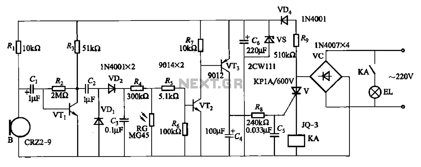
A resistor R8, capacitors Cd, and a thyristor V AC switch form a delay circuit. The lamp's lighting delay time is determined by the resistor Rs and capacitor C4, with a delay of approximately 40 seconds as indicated in...
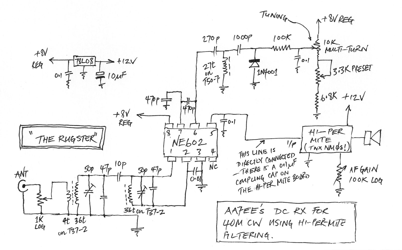
A few weeks ago, Jason NT7S mentioned the ZL2BMI DSB transceiver as a rig that might be of interest for building. He was correct; it had been seen in SPRAT, but for some reason, it had not been seriously...
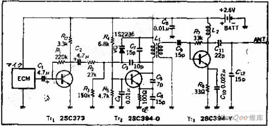
The circuit functions as a frequency modulation (FM) transmitter that operates within the 76 to 90 MHz FM radio band, commonly referred to as a wireless microphone. It receives signals through an FM radio receiver. The circuit is capable...
These filters are useful for equalisation, analysis and other tasks such as the Sound to Light converter (Project 62) or even a fully functional Vocoder. For those who have not heard of the vocoder, it is a device that...