
Four-Channel Oscilloscope Adaptor

The circuit utilizes a multiplexer to manage the input signals. A typical configuration would involve a 4-to-1 multiplexer, which is capable of selecting one of four input signals based on the binary control signals provided to its select lines. The selected input is then routed to the output, which connects to the oscilloscope channel.
In this design, each of the four signal inputs is connected to the multiplexer. The selection of the input is controlled by a binary-coded decimal (BCD) input, which can be generated using a simple binary counter or manually controlled switches. When the control signals change, the multiplexer switches the selected input signal to the output, allowing the oscilloscope to display the chosen signal.
Additional components may include resistors to protect the inputs and ensure proper signal levels, as well as capacitors for signal conditioning if necessary. The circuit can be powered using a standard DC power supply, ensuring that all components operate within their specified voltage and current ratings.
Overall, this circuit design is efficient for displaying multiple signals with minimal hardware, making it a valuable tool for engineers and technicians who require the analysis of multiple signals without the need for multiple oscilloscope channels.This circuit enables you to display four signals simultaneously using only one channel of your oscilloscope. Essentially, it switches each of the inputs t.. 🔗 External reference
Related Circuits
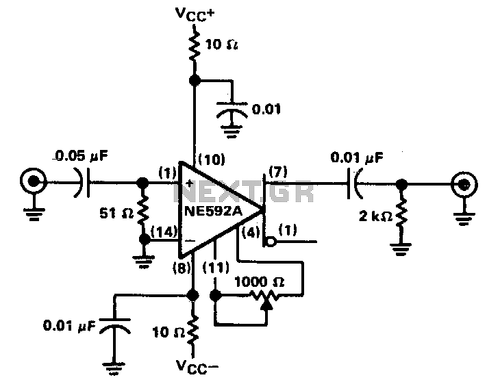
The circuit provides a voltage gain of 20 ±0.1 dB within a frequency range of 500 kHz to 50 MHz. The low-frequency response of the amplifier can be enhanced by increasing the value of the 0.05 µF capacitor connected...
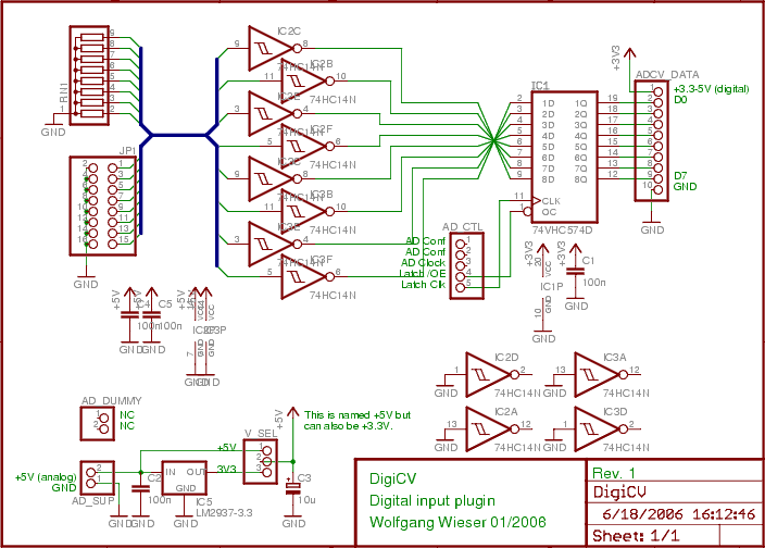
The digital input board features eight distinct digital inputs available on connector JP1. Each input is equipped with separate pull-down resistors (RN1, with a recommended value of 1 MΩ) and a Schmitt-trigger. To prevent damage from improper input voltages,...
The Xminilab-B oscilloscope is based on the Atmel AVR ATXMEGA32A4 microcontroller. It is designed as a debug board by the Gabotronis company, as noted on rlocman.ru. The Xminilab-B oscilloscope features a compact and efficient design that leverages the capabilities of...
The high voltage section of the CRT is unchanged from the original vacuum tube oscilloscope used as the basis of this design. The CRT requires shielding from the main power transformer. Cold roll steel around the CRT does not...
Dynamic flip-flops ignore pulses at their inputs that are shorter than 40 ns or do not have TTL levels. This limitation renders TTL flip-flops inadequate for capturing noise pulses with unknown durations and amplitudes. This issue is familiar to...
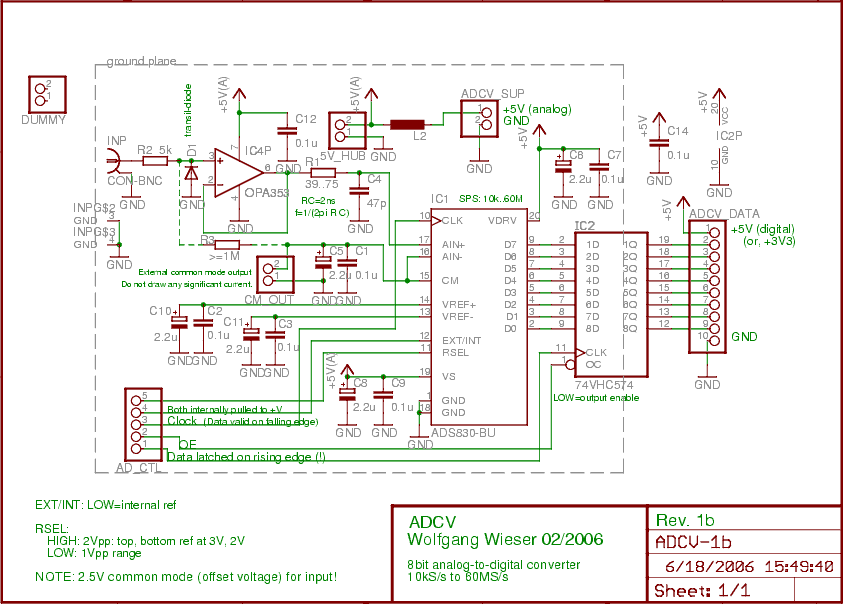
The analog input is initially connected to a fast non-inverting buffer amplifier (OPA353) configured for unity gain, which safeguards the analog-to-digital converter from out-of-range voltages. The ADS830 is an economical 8-bit analog-to-digital converter that accommodates sampling clocks ranging from...