
Four sirens sound with ic UM3561

The UM3516 is a sound generator integrated circuit that can produce a variety of tones and sound effects. It is commonly used in applications such as toys, alarms, and other electronic devices that require audio output. The operation of the circuit is straightforward: the UM3516 receives power and is configured to generate sound based on the settings applied to its pins.
Pins 7 and 8 of the UM3516 are the audio output pins, where the generated sound signals are available. These pins are connected to passive components, R1 (a resistor) and VR1 (a variable resistor or potentiometer), which are crucial for adjusting the frequency of the sound. The resistor R1 sets a baseline resistance that influences the sound output, while the variable resistor VR1 allows for real-time adjustments to the resistance, enabling the user to modify the frequency of the sound produced by the circuit.
The circuit may also include additional components such as capacitors for filtering and stabilizing the output signal, ensuring that the sound produced is clear and free from unwanted noise. The overall design of the circuit allows for flexibility in sound generation, making it suitable for various applications where sound output is required.Operation of the circuit uses a UM3516 IC IC1 number ready to create a sound all four sound at pin 7, 8 of IC1 to the R1, VR1 to take to control the frequency.. 🔗 External reference
Related Circuits
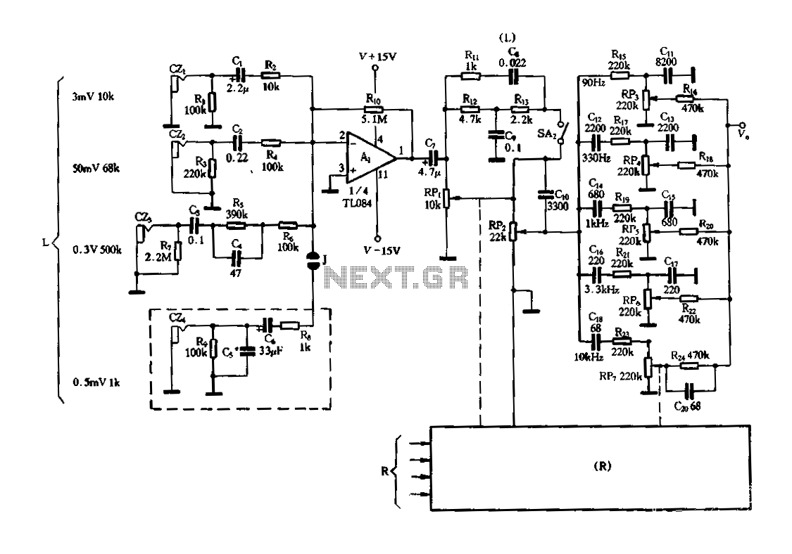
Figure 3-25 illustrates a hybrid circuit featuring four input preamplifiers. The components C1, C2, C3, and C4 can accept signals from a microphone, line, phono, and crystal head respectively. The configuration allows for the individual or simultaneous entry of...
This circuit is designed to trigger on a 1 kHz tone. To change this frequency, refer to the table below, then change the resistor and capacitor values accordingly. More: all resistors are 5 or 10 percent tolerance, 1/4-watt; all...
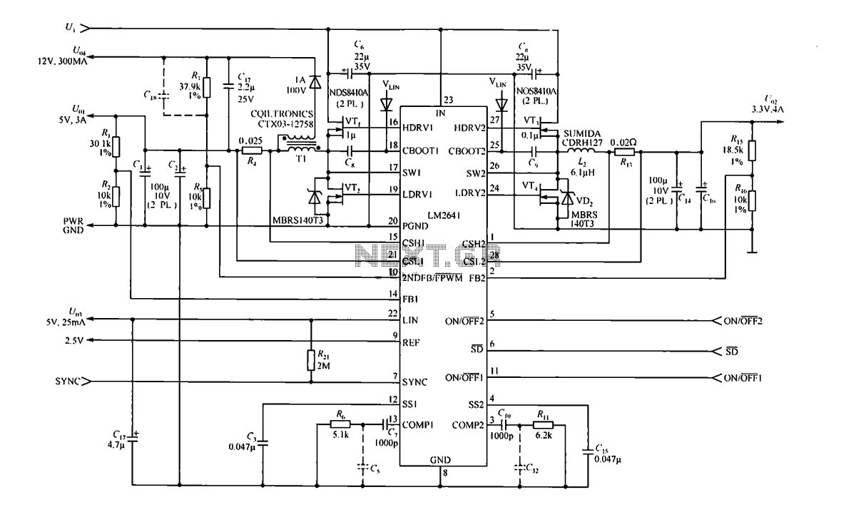
The circuit consists of the LM2641, which provides four output voltages: 5V at 3A, 3.3V at 4A, 12V at 0.3A, and 5V at 0.025A. The LM2641 is a dual adjustable step-down switching power supply controller with an input voltage...
An infra-red or wireless remote control has the disadvantage that the small, handy, remote transmitter is often misplaced. The sound operated switch has the advantage that the transmitter is always with you. This project offers a way to control...
All sound effects are generated internally by the HT2884 integrated circuit (IC). The device operates on a 3-volt battery but is compatible with any voltage ranging from 2.5 to 5 volts. Switch S1 functions as the on/off switch. The...
A 10 MHz crystal typically exhibits an impedance of 4 ohms at its series resonance and 40 kiloohms at its parallel resonance. To minimize sideband noise, the power dissipated in the crystal must be substantial; the design presented here...