
Electronic pests killing lamp circuit diagram 4

The electronic pest-killing lamp circuit is designed to effectively eliminate pests using high-voltage electrical discharges. The oscillator generates a specific frequency that is essential for the operation of the entire system. It utilizes a time-base integrated circuit (IC) to produce a square wave signal, which is then shaped by the surrounding resistors (R5 to R7) and capacitors (C7 and C8) to achieve the desired voltage levels and timing characteristics.
The diodes (VD10 and VD11) play a crucial role in protecting the circuit from voltage spikes and ensuring that the oscillation remains stable. They help in directing the current flow appropriately, preventing reverse polarity that could damage the components.
The high voltage generator is responsible for stepping up the voltage to a level sufficient to create an effective electric field for pest elimination. This component typically consists of a transformer or a series of capacitors and inductors that work together to increase the voltage from the power supply to the required level.
The LED indicator circuit serves a dual purpose: it provides visual feedback to the user regarding the operational status of the circuit and can also indicate when the device is energized. This feature is essential for safety and usability, ensuring that users can easily determine whether the device is functioning properly.
The power supply circuit is designed to convert the incoming AC voltage to a suitable DC voltage level that powers the entire circuit. It may include components such as rectifiers, filters, and voltage regulators to ensure a stable and reliable power source.
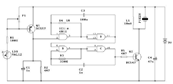
Overall, the electronic pest-killing lamp circuit is a sophisticated assembly of components that work together to create a safe and effective pest control solution, leveraging electrical principles to achieve its intended purpose.The electronic pests killing lamp circuit consists of the oscillator, control circuit, high voltage generator, LED indicating circuit and power supply circuit, and the circuit is shown as the chart. The oscillator circuit is composed of the time-base integrated circuit IC, resistors R5 ~ R7, diodes VD10, VD11 and capacitors C7, C8.
Power supply circuit is co.. 🔗 External reference
Related Circuits
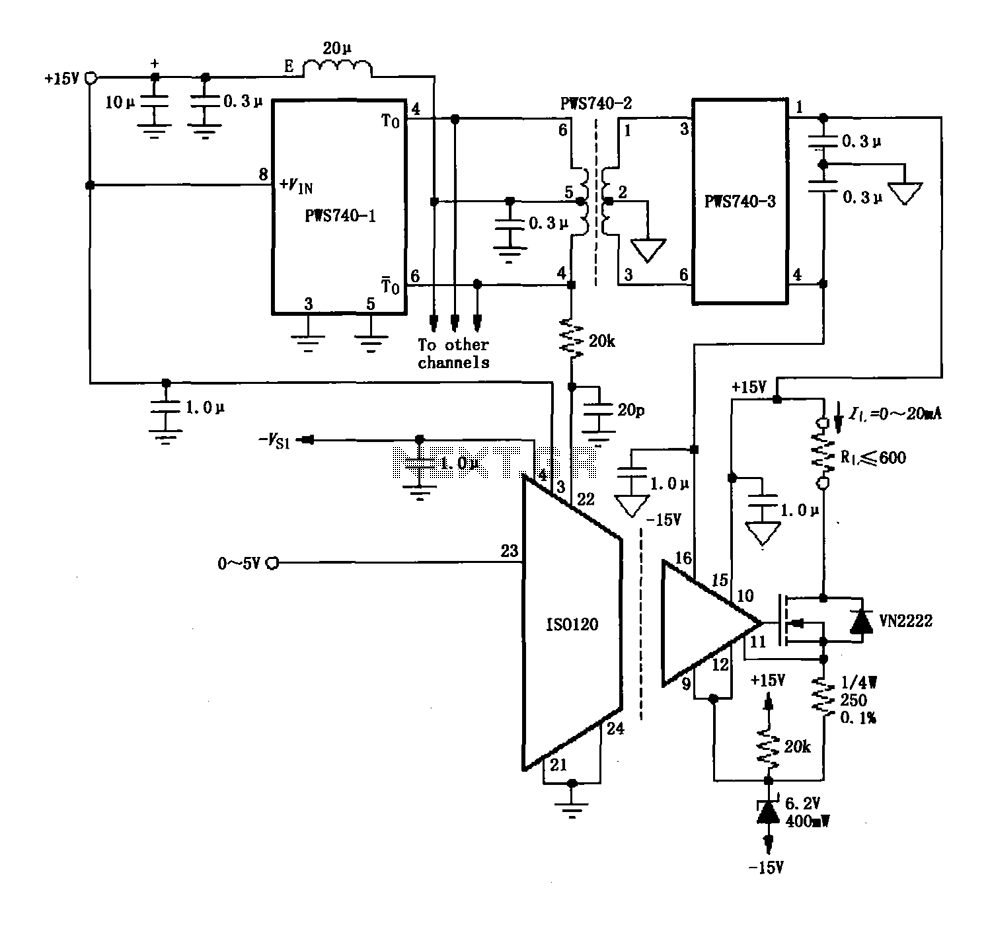
An eight-channel isolation circuit is constructed using the ISO120 and PWS740 components, designed for a 0 to 20 mA current loop. The figure illustrates only one channel, where the circuit converts a 0 to 5V input voltage into a...
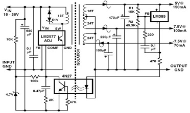
The following figure illustrates an example of a three-output flyback regulator constructed using the LM2577, which features electrical isolation between the input and output voltages. The circuit diagram specifies a voltage of 5V. Electrical isolation between the input and...
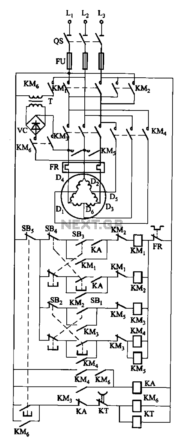
The circuit depicted in Figure 3-108 includes various control buttons: SB3 for the forward button, SI for the reverse button, SBi as the low start button, SB2 for the speed start button, and SBs for the stop button. KMs...
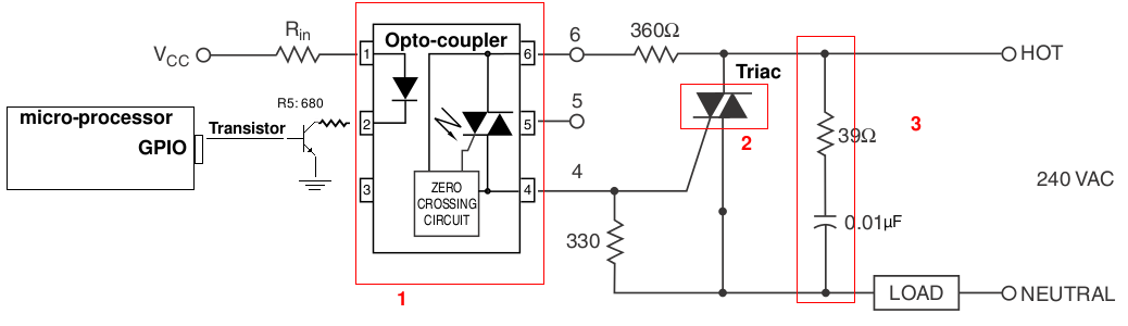
A light-dimming control system is being developed for a 240V heat lamp with a power dissipation of approximately 250W. The objective is to adjust the heat output of the lamp using control from a microprocessor. The development is based...
This light alarm schematic circuit is designed using common electronic components, as illustrated in the circuit diagram below. The light alarm circuit will activate an alarm as soon as the drawer is opened and light falls on the Darlington...
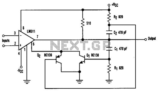
When the comparator's output transitions from low to high, the rising edge of the output pulse, differentiated by the Cl/Rl chain, activates Ql. This action blocks the comparator via its strobing input and maintains its output state for a...