
Free Running Oscillator Circuit

The described circuit operates in astable mode, which means it continuously oscillates between high and low states without requiring any external triggering. The 555 timer IC is a versatile component that can be configured in various modes, with astable operation being one of the most common applications. In this configuration, the timer generates a square wave output, which can be utilized for various applications such as clock pulses, tone generation, or LED flashing.
In the circuit, the timing interval is determined by the values of resistors Ra and Rb, as well as the capacitance of capacitor C. The frequency of oscillation (f) can be calculated using the formula:
\[ f = \frac{1.44}{(Ra + 2Rb)C} \]
This equation shows that the frequency is inversely proportional to the total resistance and the capacitance. Therefore, selecting appropriate values for Ra, Rb, and C is crucial for achieving the desired frequency of oscillation.
The 555 timer operates by charging and discharging the capacitor through the resistors. Initially, when the circuit is powered, capacitor C begins charging through Ra and Rb. As the voltage across C reaches 2/3 V+, the 555 timer's internal comparator triggers the discharge pin (pin 7), which connects C to ground, allowing it to discharge rapidly. The capacitor's discharge causes the output (pin 3) to go low, and the cycle repeats as the capacitor charges again.
Utilizing a CMOS version of the 555 timer can enhance the circuit's performance by providing lower power consumption, reduced voltage spikes, and higher frequency capabilities. This makes it suitable for battery-operated devices or applications where power efficiency is paramount.
In summary, this astable oscillator circuit using a 555 timer IC is a simple yet effective design for generating continuous square wave signals. Proper selection of component values is essential for achieving the desired oscillation frequency while ensuring reliable operation within the specified limits of the 555 timer IC.This is a circuit for oscillator using astable mode operation. The basic oscillatior is using 555 timer IC. This circuit is also give mode free running oscillator. This is the figure of the circuit. Operation of the circuit is begin, when initialy by capacitor C charged towards 2/3 V+ with Ra and Rb. When voltage on C reaches that threshold level, the discharge output in pin 7 is turning on to discharging C. Using CMOS 555 timer IC is a very wide frequency at very low of voltage spikes and dissipation can be achieved. Selections of values the Ra and Rb is limited by input leakage specification at time in pin 7, 2, and 6.
🔗 External reference
Related Circuits
This document explains how to connect lights so that they flash when the phone rings. This setup is particularly beneficial in noisy environments, such as workshops, where it is challenging to hear the phone ringing. The ring detection component...
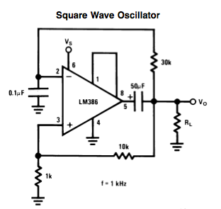
Here is a small LM386-based square-wave oscillator constructed from the following schematic. A 50k potentiometer was used in place of a 30k resistor, which functions as a pitch controller. The audio provided consists of track recordings made in Ableton...
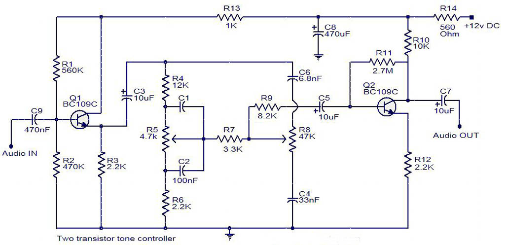
The electrical schematic diagram presented below illustrates a simple two-transistor tone controller audio circuit, which is available for free download. This circuit is based on the well-known Baxandall tone control design. Variations in the values of the transistor components...
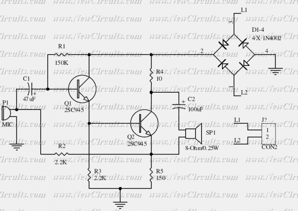
This is the basis of electronics telephone sets. You can use it to replace the talking circuit of an old telephone set with new design, better noise rejection and reliability one. Also you can use it to build a...
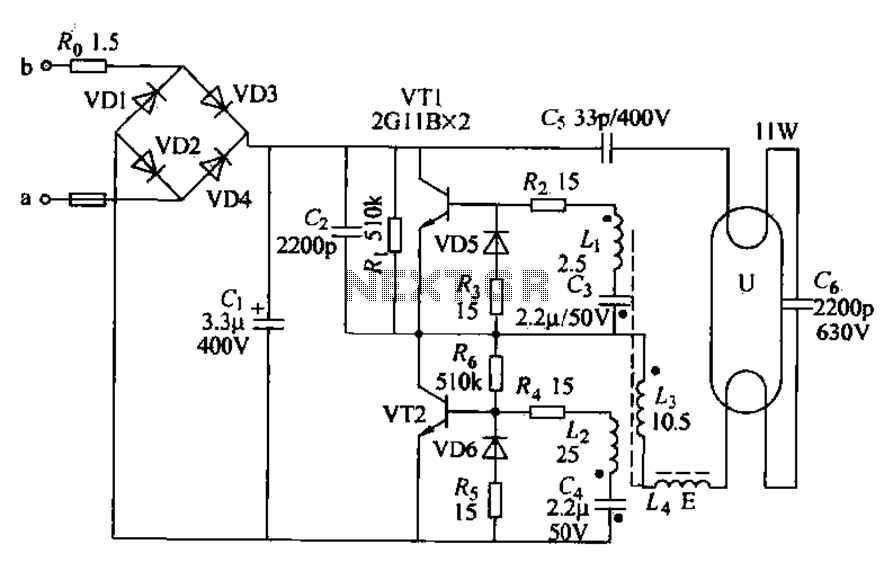
Energy-saving lamps are categorized into self-ballasted compact types and single-ended structures. They can also be classified based on appearance into various forms such as double-tube, four-tube, six-tube types, and others. The lifespan of energy-saving lamps is approximately ten times...
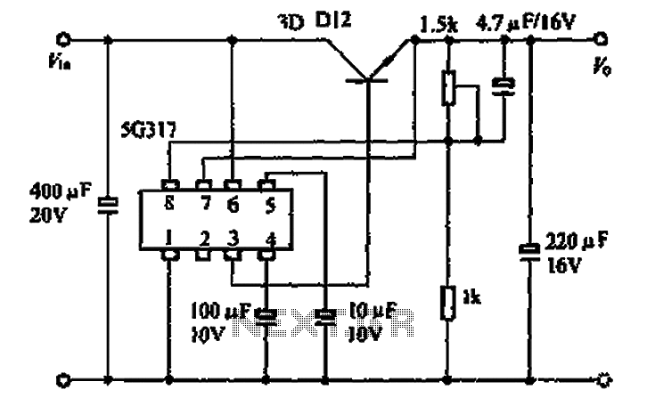
The 5G317 is an integrated voltage regulator circuit used in wiring applications for televisions. The maximum input voltage for the 5G317 should be less than 25V, while the output voltage ranges from 10V to 18V. The maximum output current,...