
tone controller circuit diagram two transistor

The two-transistor tone controller circuit operates effectively by leveraging the characteristics of each transistor to manipulate audio signals. The Q1 transistor serves as a buffer, allowing the circuit to maintain high input impedance while delivering adequate current to the subsequent stage. This configuration reduces loading effects on the audio source, ensuring that the integrity of the signal is preserved.
The second transistor, Q2, is configured to amplify the voltage level of the audio signal, facilitating further processing or output to a speaker or other audio device. The interaction between Q1 and Q2 is crucial; the emitter follower configuration of Q1 ensures that the output signal remains stable and faithful to the input signal, while Q2 provides the necessary gain to achieve the desired audio levels.
The tone control aspect of the circuit is realized through a carefully designed network of resistors and capacitors that connect the emitter of Q1 to the base of Q2. This network allows for the adjustment of frequency response, enabling users to tailor the audio output to their preferences. By varying the resistance and capacitance values, users can boost or attenuate specific frequency ranges, enhancing the listening experience.
Overall, this tone controller circuit exemplifies a practical application of transistor technology in audio processing, illustrating how fundamental electronic components can be arranged to achieve complex functionalities in sound engineering.Electrical schematics diagram shown below is a simple two transistor tone controller audio circuit free pictures for download. This electric circuit is based on the well-known Baxandal tone control plan. Deviation in the value of these electrical circuit transistor components varies the audio response of the system.
This tone controller circuit ab le to present a highest attenuation and boost of 10decibel on 10 KHz/60 Hz frequency ranges. The first transistor Q1 (C828) is energetic an emitter follower to supply sufficient current gain and input impedance. The second transistor Q2 (C828)is used to voltage amplify the signal in. The network of resistance and capacitors connected connecting emitter of Q1 and base of Q2 is used to control the tone.
🔗 External reference
Related Circuits
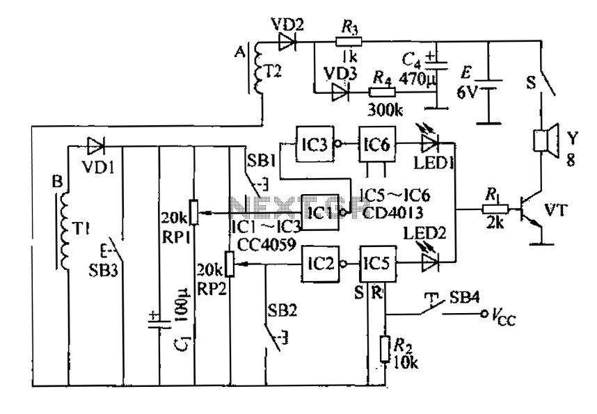
A and B are oxygen electromechanical motors operating in a two-phase and three-phase power system. Tl and T2 are wound around the exterior of two current sensing coils. Under normal power supply conditions, Tl and T2 connect to a...
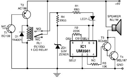
This heat detector alarm electronic project is designed using the UM3561 sound generator circuit and several common electronic components. The heat detector circuit employs a complementary pair of npn and pnp transistors to sense heat. When the temperature near...
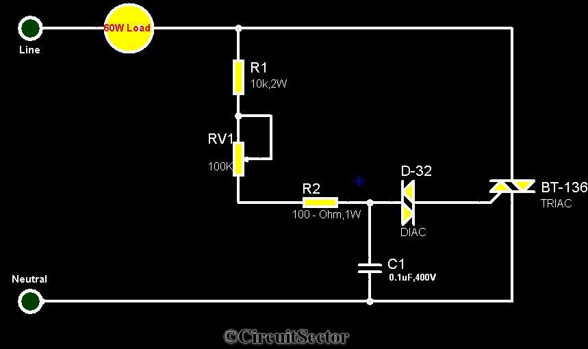
The circuit diagram presented is a triac-diac electronic fan regulator designed to reduce power consumption of electric fans, even at low speeds. Traditional resistor-inductor fan regulators tend to generate excess heat, wasting energy when the fan operates at lower...

The circuit below demonstrates the generation of a single positive pulse that is delayed in relation to the trigger input time. It is similar to a previously described circuit but utilizes two stages, allowing for control over both the...
The FM302E-I-type FM transmitter exciter is manufactured by NEC Corporation, Japan, and features a 1210 motherboard. It utilizes direct frequency modulation of the carrier signal, employing phase-locked frequency stabilization and frequency synthesis techniques. The front power amplifier is based...
This is the large controller utilized for the game Steel Battalion for the Xbox. The schematic diagram was sourced from an individual named Alpha who created it for his own use. The Steel Battalion controller is a specialized input device...