
Frequency counter BNC input schematic

The described circuit functions as a robust input interface suitable for both CMOS and TTL logic families. The incorporation of over-voltage and under-voltage protection ensures that the circuit can withstand voltage levels beyond its specified operating range, thus safeguarding downstream components from potential damage.
Schmitt triggers are a critical component in this design, providing hysteresis that enhances the circuit's tolerance to noisy signals and allows for reliable operation even when input signals have slow rise and fall times. This feature is particularly beneficial in high-speed applications where signal integrity can be compromised by slow transitions.
The circuit's capability to operate at frequencies up to 30 MHz indicates that it can be effectively used in high-speed digital applications, making it suitable for interfacing with various sensors, microcontrollers, and communication devices.
For implementation, the design may include a series of resistors and capacitors to set the appropriate time constants for the Schmitt trigger inputs, ensuring optimal performance. Additionally, careful consideration should be given to the selection of input protection components, such as transient voltage suppressors (TVS) or zener diodes, to effectively clamp any excessive voltage levels while minimizing signal distortion.
Overall, this circuit design represents a versatile solution for applications requiring reliable logic level interfacing with inherent protection features and high-speed performance capabilities.This is a CMOS-compatible (and hopefully also TTL) input featuring over- and under-volatage protection. Schmitt triggers are used to allow for input with long transition times. Verified to work up to 30MHz. 🔗 External reference
Related Circuits
The circuit of a loop sensor-based simple security alarm is described here. The sensor loop consists of a short length of thin enamelled copper wire. The loop sensor security alarm operates on the principle of detecting interruptions in the circuit...
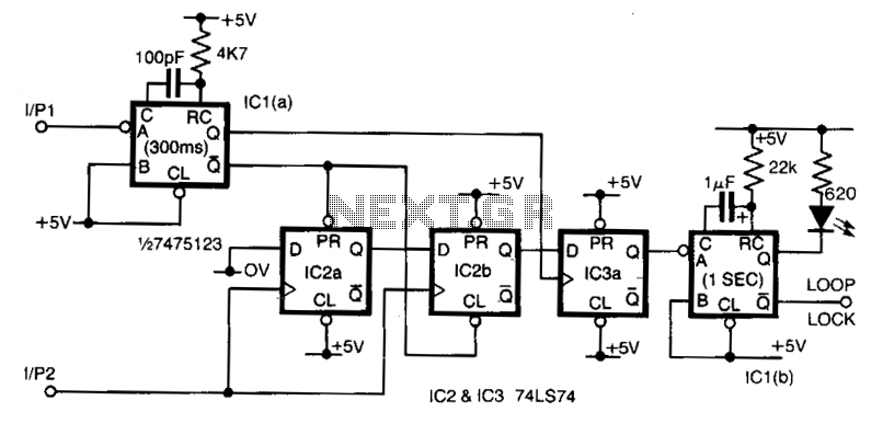
Input 1 functions as a gating period, during which a single rising edge on input 2 produces a logic 1 output. Any other input that indicates non-identical frequencies results in a logic 0 output. IC1a converts input 1 into...
The Light Switch with Relay is a series of electronic switches that are controlled by light intensity. This circuit can automatically control lighting, turning the lights on when ambient light levels decrease. The threshold for light activation in the...
This frequency doubler using a single 4069 hex inverter IC, a frequency doubler can be constructed to give an output pulse train whose frequency is twice that of a squarewave input signal. The signal is applied to the input...
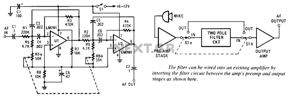
This variable-frequency audio bandpass filter is constructed using two 741 operational amplifiers (op amps) connected in cascade. Both op amps are configured as identical RC active filters, enhancing the selectivity of the overall circuit. The filter has a tuning...
This circuit is designed to indicate, via a flashing LED, when room noise exceeds a predetermined threshold, selectable from three fixed levels: 50 dB, 70 dB, and 85 dB. The circuit utilizes two operational amplifiers to amplify the sound...