
LED Audio VU Meter Circuit

The LED meter circuit based on the LM3915 IC is designed for efficient and effective audio level monitoring. The LM3915 is a bar graph/LED dot display driver capable of displaying audio levels with high accuracy. Its logarithmic response is particularly suited for audio applications, as human perception of sound intensity is logarithmic in nature.
The circuit operates by receiving an audio input signal, which is then processed by the LM3915. The IC translates the input voltage into a corresponding output that drives the LEDs. In normal operation, the first eight LEDs (L1 to L8) illuminate to indicate audio levels, providing a visual representation of the signal strength. When the audio level exceeds a predetermined threshold, the last two LEDs (L9 and L10) light up in red, signaling an overload condition. This feature is crucial for preventing distortion and potential damage to audio equipment.
The inclusion of diode D3 ensures that the voltage supplied to the LEDs is stable and not subject to fluctuations that could arise from filtering. This allows for a more responsive display, as the LEDs can react quickly to changes in the audio signal without the lag that can occur with fully smoothed DC supplies. Capacitor C1 plays a vital role in maintaining the stability of the circuit by preventing oscillations that could lead to erratic LED behavior.
The power supply design, utilizing a 15-0-15 transformer, is optimized for low power consumption. The transformer provides the necessary AC voltage, which is then rectified and regulated to supply the LM3915 and the LEDs. The choice of a small transformer is justified by the low peak current requirement of 120mA DC, making the circuit energy-efficient.
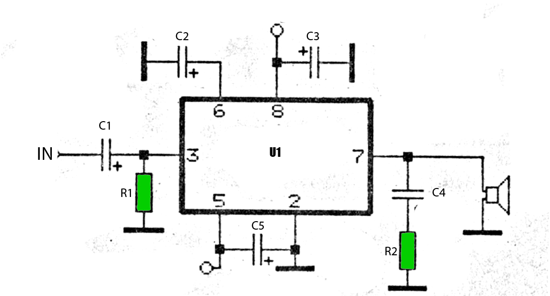
Overall, this LED meter circuit serves as an effective tool for visualizing audio levels in various applications, from home audio systems to professional sound equipment, ensuring that users can monitor audio performance accurately and avoid overload situations.The LED meter circuit is simpler and smaller than its analogue counterpart, and is very common in audio equipment. This circuit is based on LM3915 IC and uses the logarithmic version. This circuit is using a single IC and a few discrete components. The extra diode (D3) is included to ensure that the DC to the LEDs is almost unfiltered. C1 is inclu ded to make sure the IC does not oscillate, and is not a filter capacitor. This allows a higher LED current with lower dissipation than would be the case if the DC were fully smoothed, and full smoothing would also require a much larger capacitor. This is the figure of the LED audio VU meter circuit; How is this circuit work We will explain with simple ways.
L1 to L8 will normally be green (normal operating range) and L9 and L10 should be red (indicating overload). This gives a 6dB overload margin when the unit is calibrated as described below. As shown, full scale sensitivity (with VR1 at maximum) is 12 Volts peak (approximately 8. 5 volts RMS). This is designed for direct connection to the speaker output of an amplifier, but is still suitable for use with preamps if the sensitivity is changed.
Power comes from a 15-0-15 transformer (connected to AC1-Com-AC2). You can generally use the smallest one available, as average power is quite low. The peak current is about 120mA DC, so a 5VA transformer will be sufficient to power two meter circuits. One 15V winding goes to the terminal AC1, the other goes to AC2 and the centre tap is connected to Com (Common).
🔗 External reference
Related Circuits
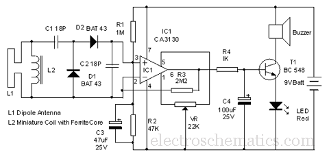
This circuit is designed to detect microwave sources, such as microwave ovens, satellite communication devices, and mobile phones. It provides audio-visual indications when microwaves in the gigahertz band are detected. Microwaves are a form of electromagnetic radiation with frequencies...
This precise one-pulse-per-second clock is constructed using a few common components and is driven by a 50 or 60 Hertz mains supply without any direct connection to it. A beep or a metronome-like click, along with a visible flash,...
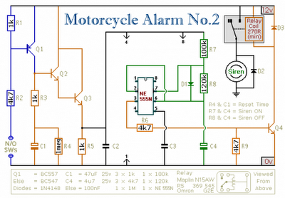
Any number of normally-open switches may be utilized. Install "tilt" switches that close when the steering is moved or when the bike is lifted off its side-stand or pushed forward off its centre-stand. Employ micro-switches to secure removable panels...
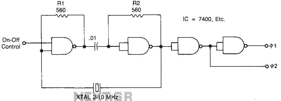
Temperature-stable resistors R1 and R2 are used in NAND gate configurations, ensuring that the switches operate in the linear region. Capacitor C1 functions as a DC component at the operating frequencies. Additionally, the impedance must remain below 0.1 ohm....
The circuit is designed to operate with an audio power amplifier that uses 18V-0V-18V power rails. The specific voltage is not critical, but the feedback is referenced to an LED chain connected to a 12V rail, necessitating a separate...
The car power amplifier utilizes the SI1050GL integrated circuit (IC) as the primary amplification component. It delivers an output power of 50 Watts at an 8-ohm mono impedance. The amplifier operates with a DC voltage of up to 25...