
Frequency Counter Tachometer

The tachometer circuit is designed to provide a direct digital readout of rotational speed in hertz, facilitating easy interpretation of the measurements. The circuit utilizes a frequency-to-voltage converter, which translates the input frequency derived from the rotating object into a proportional voltage. This voltage is then processed by an analog-to-digital converter (ADC) to display the frequency in hertz on a digital screen.
The gating time, which is the duration over which the input signal is measured, is critical in determining the accuracy of the readings. By synchronizing the conversion time with the gating time, the circuit ensures that the frequency measurement reflects the true operational speed of the motor or shaft being monitored.
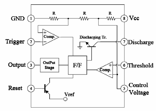
To implement this circuit, essential components include a microcontroller to handle the ADC and display interface, a frequency sensor (such as a Hall effect sensor or an optical encoder) to detect the rotational speed, and a display module (such as a seven-segment display or an LCD) to present the output. The microcontroller is programmed to initiate the ADC at the end of each gating interval, ensuring that the displayed value corresponds to the frequency measured during that time frame.
The tachometer circuit can be powered by a standard DC power supply, and it is advisable to incorporate filtering capacitors to stabilize the power supply voltage. Additionally, proper signal conditioning may be required to filter out noise from the frequency sensor, ensuring that the readings are accurate and reliable.
Overall, this tachometer circuit design provides a straightforward yet effective solution for measuring rotational speed in real-time, making it suitable for various applications in industrial and automotive settings.For convenient reading, the display of this tachometer circuit show inthe reading in hertz directly.? The conversion time will be equal to the gating time,. 🔗 External reference
Related Circuits
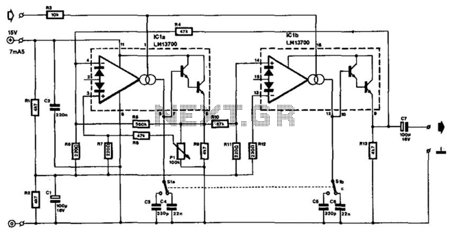
The frequency of this sine-wave oscillator is determined by a direct voltage, U, ranging from 0 to 15 V. The distortion in output signals of up to 10 Vpp does not exceed 1%. When the output is reduced using...
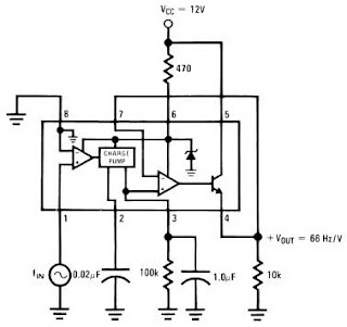
The LM2917 IC chip is specifically designed as a Frequency to Voltage Converter. It requires only a few external components for its operation. The datasheet for the LM2917 IC includes several application examples of the Frequency to Voltage Converter....
This circuit functions as a low-frequency warning device. The output from the oscillator generates a square wave signal, which is utilized to operate lamps or small relays. The circuit alternately flashes two incandescent lamps. The low-frequency warning device circuit typically...
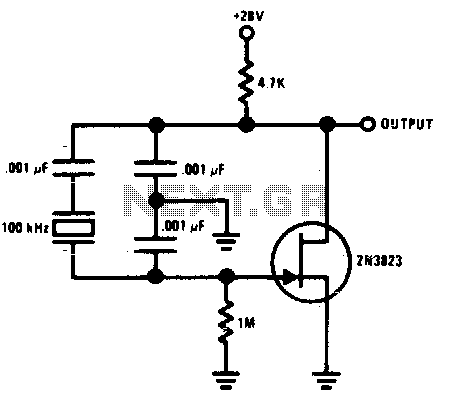
This Colpitts crystal oscillator is ideal for low-frequency crystal oscillator circuits. Excellent stability is assured because the 2N3823 JFET circuit loading does not vary with temperature. The Colpitts crystal oscillator is a type of electronic oscillator that utilizes a combination...
A 1 Hz pulse frequency generator utilizes the widely used timer IC 555 configured as an Astable Multivibrator. The output pulses can be visually indicated by an LED. An Astable Multivibrator, often referred to as a free-running Multivibrator, is...
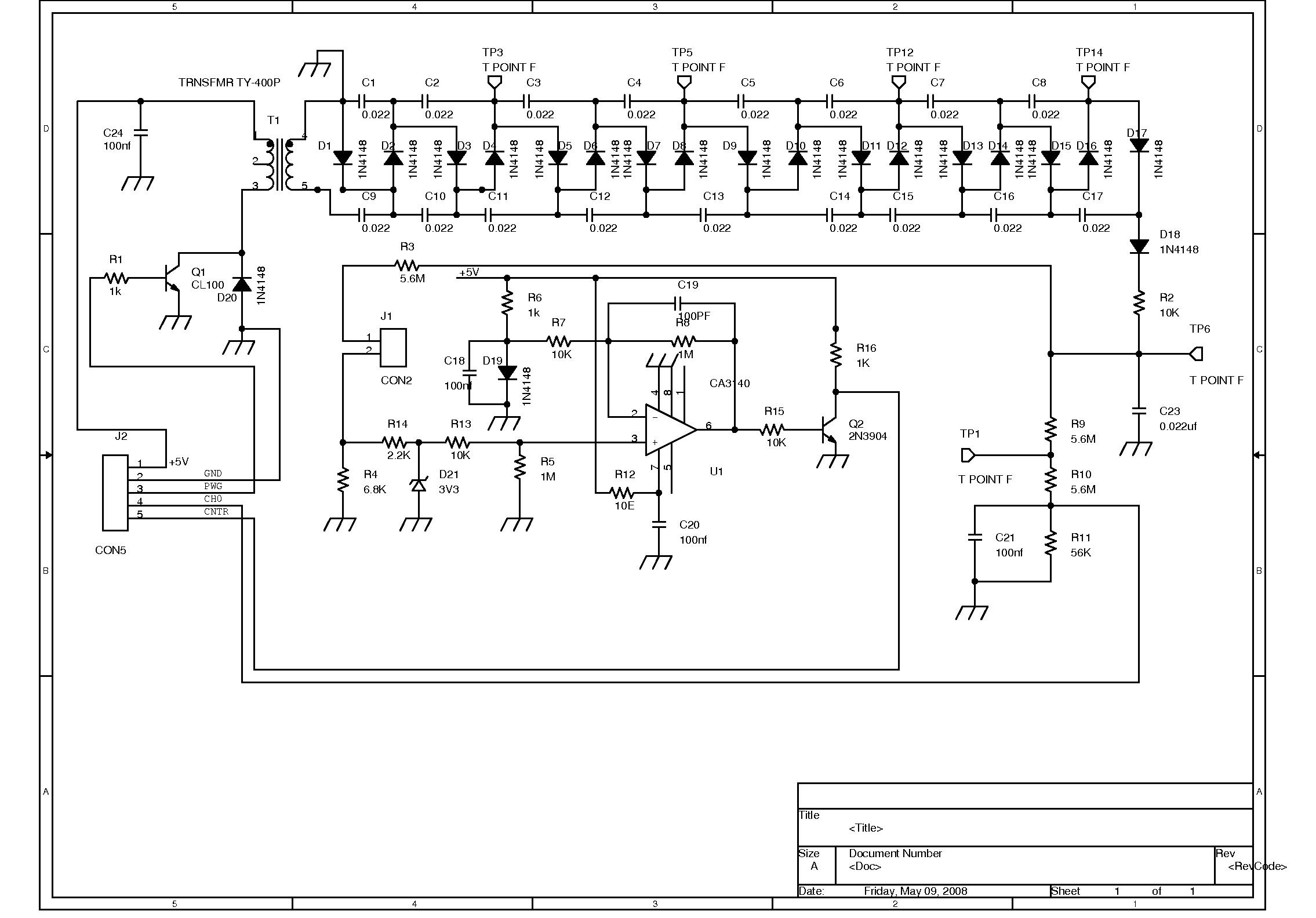
The GM Counter Accessory is capable of generating a DC voltage of up to 1 kV using a 5V pulse produced on the PWG. The voltage is controlled by varying the duty cycle of the pulse. A high voltage,...