
Frequency divider

This circuit is designed to mitigate unwanted spikes that occur in the center of a sawtooth waveform. The sawtooth wave, characterized by its linear rise and abrupt fall, is commonly used in various applications such as signal generation and waveform synthesis. However, spikes can distort the intended signal, leading to inaccuracies in performance.
The circuit achieves spike elimination through a triggering mechanism. This involves monitoring the sawtooth waveform and identifying the precise moment when a spike occurs. A comparator or a similar device can be employed to detect these anomalies. Once a spike is identified, a control signal is generated to modify the waveform, effectively suppressing the spike.
The design may incorporate operational amplifiers to enhance the detection sensitivity and speed of response. Additionally, filtering components such as capacitors and resistors can be included to smooth out the waveform further, ensuring that the output remains clean and stable.
In summary, this circuit provides a robust solution for spike elimination in sawtooth waves, enhancing the quality and reliability of the signal for various electronic applications.Spikes in the center of a sawtooth wave are eliminated in this circuit by triggering at.
Related Circuits
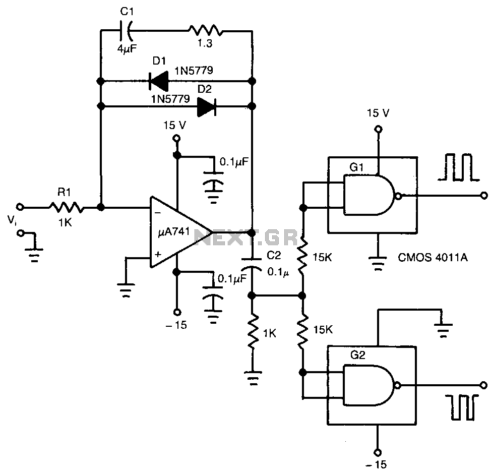
The input voltage, V1, causes capacitor C1 to charge, producing a ramp voltage at the output of the 741 operational amplifier. Diodes D1 and D2 are four-layer devices. When the voltage across C1 reaches the breakover voltage of either...
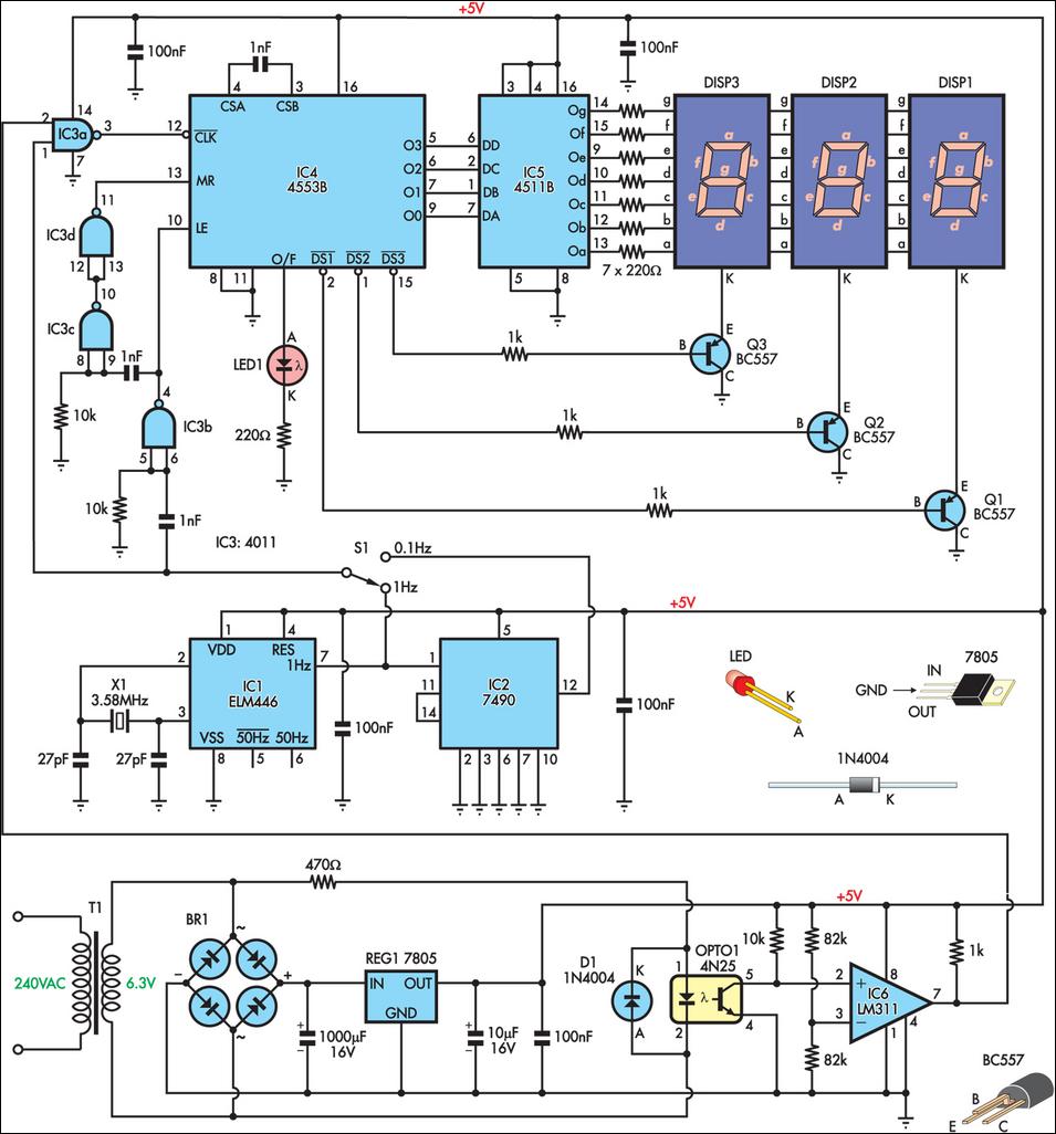
This is a simple frequency counter designed to monitor the 240VAC mains supply. It has a frequency range of 0-999Hz, making it suitable for use with 400Hz equipment as well. Standard TTL/CMOS logic is utilized for the counters and...
The pulse width of the compact pulse cum frequency modulator can be adjusted by changing the switch-over point of comparator IC1 using a control voltage through resistor R1. The hysteresis of the IC is set by resistors R3 and...
To ensure the circuit functions properly, it is crucial to correctly configure the fuse bits within the AVR microcontroller. These fuse bits can be set using the programmer employed to upload the software. For those interested in the technical...
The circuit comprises a Microchip PIC 16F84 microcontroller and an LCD text module. The author claims that this counter can measure frequencies ranging from 400 Hz to 50 MHz. A faster version, the 20 MHz PIC 16F84A-20I/P, was utilized,...
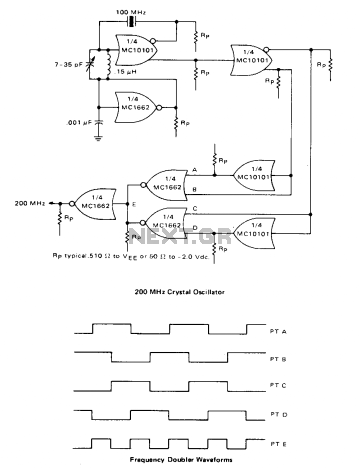
A high-speed oscillator can be created by integrating an MECL 10 crystal oscillator with an MECL III frequency doubler. One section of the MC10101 is configured as a 100 MHz crystal oscillator, with the crystal placed in series within...