
Frequency counter 400Hz to 50MHz with PIC 16F84

The design features a Microchip PIC 16F84 microcontroller, which serves as the core processing unit for frequency measurement. This microcontroller is equipped with a 14-bit instruction set and operates at a maximum clock speed of 20 MHz, allowing for efficient data processing and control tasks. The LCD text module provides a user-friendly interface for displaying frequency measurements in real-time.
The circuit is capable of measuring a wide frequency range, from 400 Hz to 50 MHz, making it suitable for various applications in electronics and telecommunications. The use of the PIC 16F84A-20I/P variant enhances performance, enabling it to accurately count signals up to 80 MHz. This is achieved through careful programming of the microcontroller, which involves configuring input capture features to sample the oscillator output effectively.
To facilitate the operation, the circuit includes necessary passive components such as resistors and capacitors for signal conditioning, as well as power supply decoupling. The microcontroller interfaces with the LCD module using a parallel communication protocol, allowing for direct data transfer and display updates.
The schematic design should include connections for the microcontroller's oscillator circuit, which typically involves an external crystal or resonator to ensure stable clock performance. Additionally, input pins must be configured to receive frequency signals, with appropriate protection measures against voltage spikes or noise.
Overall, this frequency counter circuit represents a robust solution for high-frequency measurements, leveraging the capabilities of the PIC microcontroller and an LCD display for effective visualization of results.It consists only from Microchip PIC 16F84 cpu and LCD text module. Author states that this counter is capable metering frequencies from 400Hz to 50MHz. I used faster, 20MHz version of 16F84A-20I/P, and it managed to count 80MHz oscillator output. 🔗 External reference
Related Circuits
This is a simple use of the PIC 16F84 about a diode tester. Test procedure: We set "1" to PB0 and "0" to PB3. If the diode is ok and opens, then at PA0 we have "1". If PA0...
This function initializes a specific port for keypad operation. A global variable for the keypad port must be defined before using this function. The port needs to be initialized prior to calling the function. It reads the key when...
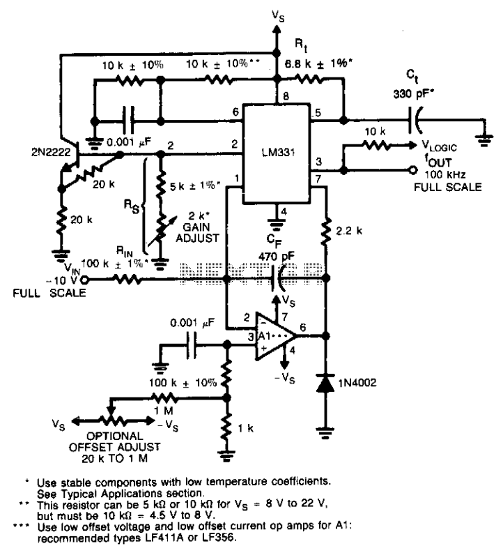
This circuit utilizes a conventional operational amplifier in conjunction with a feedback capacitor (CF) to perform integration. When the output of the integrator exceeds the nominal threshold level at pin 6 of the LM131, it triggers the timing cycle....
A voltage-to-frequency converter (VFC) circuit is illustrated in the schematic diagram below. The circuit utilizes a 555 integrated circuit (IC) as the central component of its operation. The voltage-to-frequency converter (VFC) is a crucial electronic circuit that converts an input...
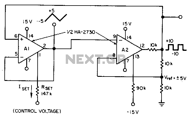
This circuit utilizes a programmable operational amplifier, specifically the HA2730, which is a two-amplifier monolithic chip featuring independent programming ports for each amplifier. The parameters of the amplifiers, including the slew rate, vary linearly based on a set current....
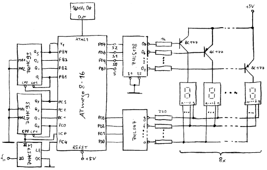
In counter mode, it provides 1 Hz resolution up to 100 MHz. In timer mode, the maximum resolution is 0.0000001 Hz up to 1 Hz. The resolution decreases by one digit for each additional decade. Multiple frequency updates per...