
Frequency to Voltage converter circuit based on the TC9400 IC

The TC9400 is a versatile integrated circuit that converts frequency signals into corresponding voltage levels. This functionality is crucial in various applications, such as signal processing, instrumentation, and control systems. The circuit can be configured to operate in dual supply or single supply modes, offering flexibility depending on the specific requirements of the application.
In the dual supply configuration, the TC9400 typically requires a positive and a negative voltage supply, allowing it to handle bipolar input signals effectively. This configuration is beneficial when dealing with AC signals or when the input frequency can swing above and below ground. The circuit design will include appropriate bypass capacitors to ensure stable operation and minimize noise.
Conversely, the single supply configuration simplifies the power requirements and is suitable for applications where the input signal is always above ground. This setup often involves biasing the input signal to ensure that it remains within the operational range of the TC9400, allowing for accurate frequency-to-voltage conversion.
The basic operation of the TC9400 involves the input frequency being applied to the input pin of the IC, which then generates an output voltage proportional to the frequency. The output voltage can be calibrated using external resistors and capacitors, allowing for fine-tuning of the circuit to meet specific application needs. The circuit may also include additional components such as operational amplifiers for further signal conditioning or filtering to enhance performance.
Overall, the TC9400 frequency to voltage converter circuit is a reliable and efficient solution for converting frequency signals into voltage levels, adaptable to various power supply configurations and application requirements.A simple frequency to voltage converter circuit designed around the TC9400 F to V / V to F converter IC. Dual and single supply versions are given here.. 🔗 External reference
Related Circuits
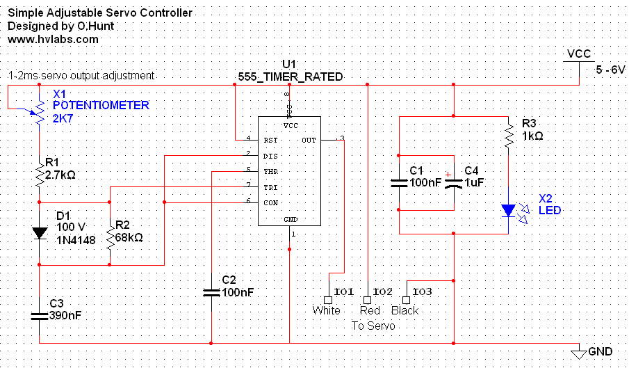
The circuit is straightforward. A 555 timer integrated circuit (IC) is utilized to generate a pulse every 20 milliseconds, with a duty cycle ranging from 5% to 10% (1-2 milliseconds). All components used are standard parts. This circuit can...
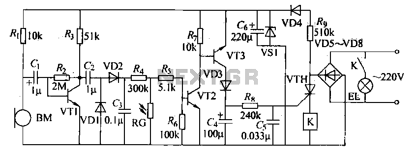
The voice circuits discussed in this section operate such that during daylight or in bright conditions, the voice-activated switch remains off, preventing the lamp from lighting. Conversely, in low-light conditions or at night, the sound control switch is activated....
Converting current into voltage is undesirable for two reasons: first, an impedance is inserted into the measuring line, causing an error; second, amplifier offset voltage is also amplified, leading to a subsequent loss of accuracy. The use of a...
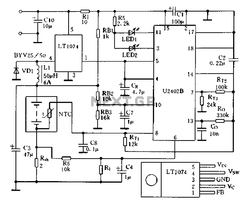
Charging circuit from the DC power supply switching power supply control The charging circuit described is designed to operate with a DC power supply, utilizing a switching power supply control mechanism. This type of circuit is commonly employed in applications...
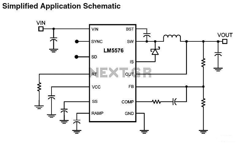
LM5576MHX absolute maximum ratings: (1) VIN to GND: 76V; (2) BST to GND: 90V; (3) PRE to GND: 76V; (4) SW to GND (Steady State): -1.5V; (5) BST to VCC: 76V; (6) SD, VCC to GND: 14V; (7) BST...
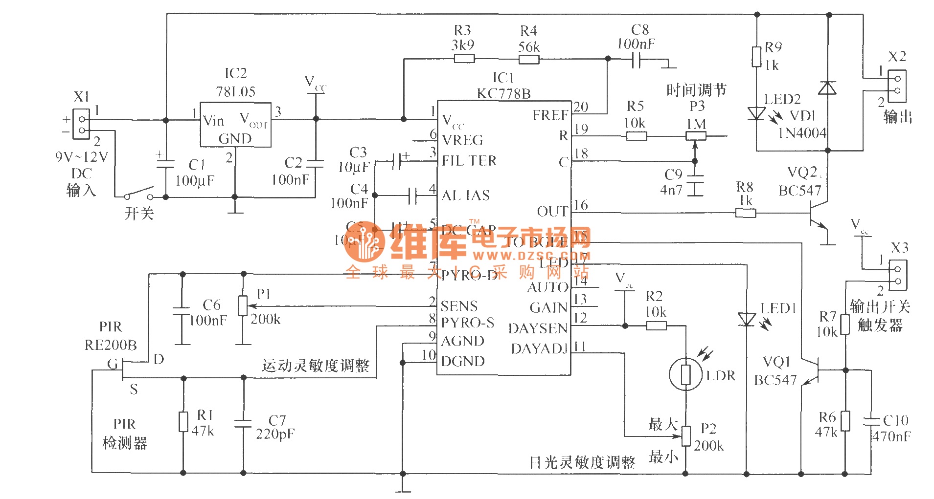
The core component of the motion detection circuit is the motion detection chip IC1 (KC778B). The signal frequency from the PIR sensor is low, ranging from 0.1Hz to 10Hz, while the bandwidth is quite broad, which the chip will...