
Frequency electromagnetic RBI timer CD4017

The electromagnetic RBI timer is designed to provide a reliable timing mechanism for educational physics experiments. Its straightforward construction allows for easy integration into classroom settings, enabling students to engage with fundamental concepts of electromagnetism and timing. The timer's operation is based on a vibrating needle mechanism, which is crucial for recording precise intervals on a magnetic tape.
The primary functionality of the timer hinges on its ability to produce a consistent dot interval of 0.02 seconds. This short interval can be advantageous in certain scenarios but may not suffice for experiments requiring longer timing units. To address this limitation, the timer utilizes a counting method where only every fifth point recorded is considered significant, effectively translating the rapid dot interval into a more manageable time frame of 0.1 seconds. This method aids in reducing the clutter of unnecessary data while still providing a means to track the timing of events accurately.
The J0203-1 circuit exemplifies modern advancements in electronic frequency technology, which enhances the timer's performance by allowing for adjustable timing cycles. The power inverter incorporated in the design ensures that the timer can adapt to various experimental setups, catering to a diverse range of educational needs. Overall, the electromagnetic RBI timer serves as a vital tool in the educational landscape, facilitating the exploration of timing and electromagnetic principles in a practical, hands-on manner.Electromagnetic RBI timer simple structure, low price, high school physics experiment teaching is one of the most widely used instruments. The main disadvantage of the experime nt produced large errors electromagnetic RBI timer. The reason, first electromagnetic RBI timer vibration needle in RBI during tape recording will hinder movement, so that the moving speed of the tape is slowed down; electromagnetic RBI timer is followed by the step-down after AC drive, the dot interval of one cycle of alternating current, ie 0.02s. For many experiments, this time interval is too short, because generally the 0.1S as the time unit. In the experiment, you need to vibrating needle RBI timer recording tape recording played point is called the point, and artificial selection from the recording point out, point for point count is called timing.
On the tape recorded every five points only count as a point, that point is the interval count 0.02s 5 0.1s. Thus, most of the experiments and did not record a point contribution, thus reducing unnecessary records point.
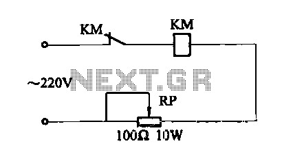
Circuit shown in Figure RBI timer for J0203-1 type currently used in a large number of secondary schools, the use of electronic frequency technology, the design of a power inverter that J0203-1 type vibrator RBI timer pin can be in a variety of different cycles RBI timing.
Related Circuits
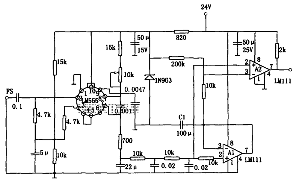
The sensitive frequency demodulation circuit utilizes the LM565 integrated circuit in a phase-locked configuration, allowing it to track frequency offsets across a wide range. However, at small frequency offsets, the signal can produce a minimal demodulated output, causing the...
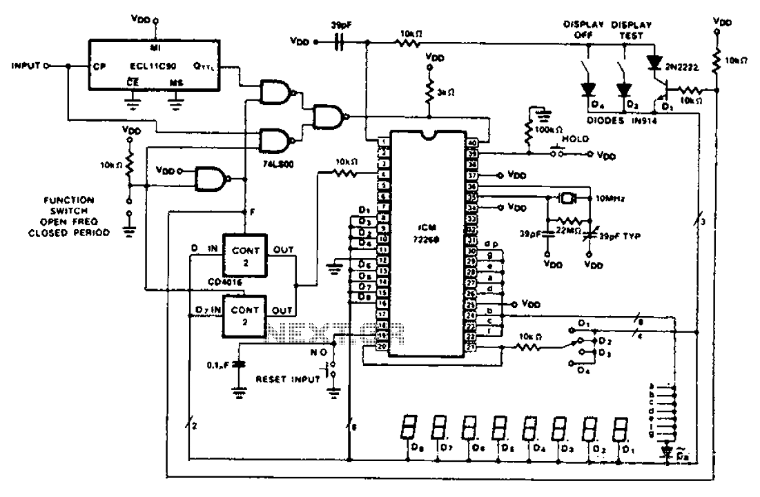
A CD4016 analog instrument is utilized as a multiplexed digital output, transferring the output function back to the input. The CD4016 operates as a digitally controlled analog transmission gate, eliminating the need for a digital output level shift. Alternatives...
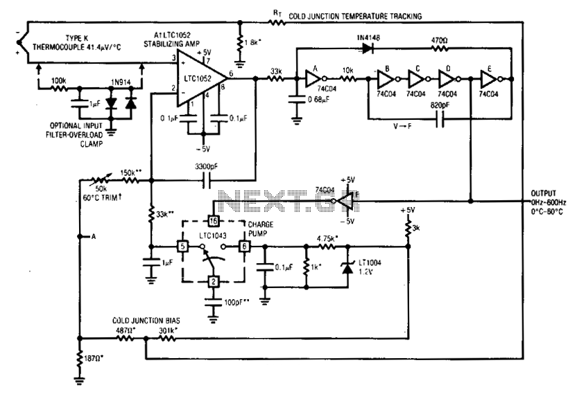
Al's positive input is biased by the thermocouple. Al's output drives a basic voltage-to-frequency (V-F) converter, which consists of 74C04 inverters and related components. Each V-F output pulse results in a fixed amount of charge being transferred from a...

The circuit illustrated in Figure 4 is an AC timing circuit designed to operate for 4 hours. It utilizes the BH4024, a 7-stage serial binary counter/divider, in conjunction with a 555 timer circuit. The circuit is activated by a...
This tester is designed to locate stray electromagnetic (EM) fields. It can easily detect both audio and RF signals up to frequencies of around 100 kHz. However, it is important to note that this circuit is not a metal...
An electromagnetic vibration table or feeder is designed to move small objects along a specific track or cylindrical path through forced vibrations. This device can be custom-built to facilitate the movement of items along a rail tube. The vibration...