
Electromagnetic Field Probe with Meter Outputs

The circuit employs a simple yet effective design for detecting electromagnetic fields, relying on the principles of electromagnetic induction and amplification. The op-amp serves as the initial amplifier, boosting the weak signals picked up by the probe. The 150 pF capacitor plays a critical role in shaping the frequency response of the circuit, ensuring that it is sensitive to the desired frequency range while filtering out unwanted higher frequencies.
The BC109C transistor is utilized to further amplify the AC voltage output from the op-amp. This transistor is known for its low noise characteristics, making it suitable for audio applications. Following amplification, the AC signal undergoes full-wave rectification, which converts it into a DC signal suitable for measurement. The rectification process involves diodes that allow current to flow in one direction, thus producing a pulsating DC voltage that is then smoothed by the capacitor to provide a stable reading on the panel meter.
The use of stereo headphones as an optional monitoring tool enhances the user experience by providing real-time audio feedback, allowing for a more intuitive understanding of the electromagnetic fields being detected. The inclusion of a radial inductor and screened cable is essential for minimizing interference and ensuring accurate readings. The design allows for flexibility in the probe setup, accommodating various configurations depending on user needs.
In practical applications, the tester can be used to identify sources of electromagnetic interference in audio equipment, helping to troubleshoot issues related to hum and noise. It is also useful for educational purposes, demonstrating fundamental concepts of electromagnetism and circuit design. The device's ability to detect stray fields and provide visual and audio feedback makes it a valuable tool for both hobbyists and professionals in the field of electronics.This tester is designed to locate stray electromagnetic (EM) fields. It will easily detect both audio and RF signals up to frequencies of around 100kHz. Note, however that this circuit is NOT a metal detector, but will detect metal wiring if it conducting ac current. Frequency response is from 50Hz to about 100kHz gain being rolled off by the 150p capacitor, the gain of the op-amp and input capacitance of the probe cable. Stereo headphones may be used to monitor audio frequencies at the socket, SK1. I used a radial type inductor with 50cm of screened cable threaded through a pen tube. The cable may be used with a plug and socket if desired. My probe is shown below: The output signal from the op-amp is an ac voltage at the frequency of the electro-magnetic field. This voltage is further amplified by the BC109C transistor, before being full wave rectified and fed to the meter circuit.
The meter is a small dc panel meter with a FSD of 250uA. Rectification takes place via the diodes, meter and capacitor. If you have access to an audio signal generator you can apply an audio signal to the windings of a small transformer. This will set up an electromagnetic field which will be easily detected by the probe. Without a signal generator, just place the probe near a power supply, mains wiring or other electrical device.
There will be a deflection on the meter and sound in the headphones if the frequency is below 15KHz. Switch on, plug in headphones (optional) and move the probe around. Any electrical equipment should produce a hum and indicate on the meter. I remember once building a high gain preamp (for audio use). I made a power supply in the same enclosure. The preamp worked, but suffered from an awful mains hum. This was not directly from ripple on the power supply as it was regulated and well smoothed. What I had done was built the audio circuit on a small piece of veroboard, and placed it within a distance that was less than the diameter of the transformer. The transformers own electromagnetic field was responsible for the induced noise and hum. I should however note, that this was when I was new to electronics with very little practical experience.
You can now buy toroidal transformers which have a much reduced hum field. 🔗 External reference
Related Circuits
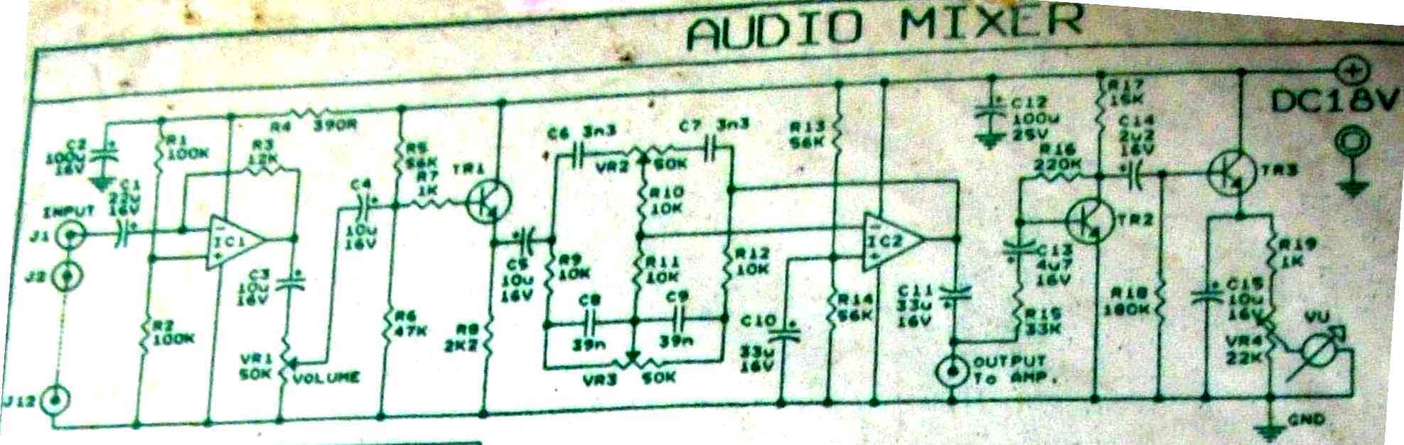
This is audio mixer circuit. The circuit is for one channel input, if you need, for example 5 channel mixer, then you need to build 5 similar circuits. The audio mixer circuit described is designed to handle a single channel...
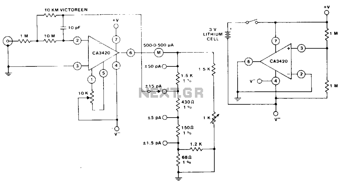
The circuit utilizes the extremely low input current (0.1 pA) of the CA3420 BiMOS operational amplifier. With only one 10 megohm resistor, it achieves a range from ±50 pA maximum to a full-scale sensitivity of ±1.5 pA. Additionally, by...
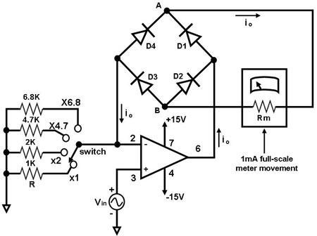
The primary component of this circuit is an operational amplifier (such as the 741 or 351), configured as an amplifier with a feedback circuit that consists of a diode bridge full-wave rectifier. An ammeter is connected to the rectifier...
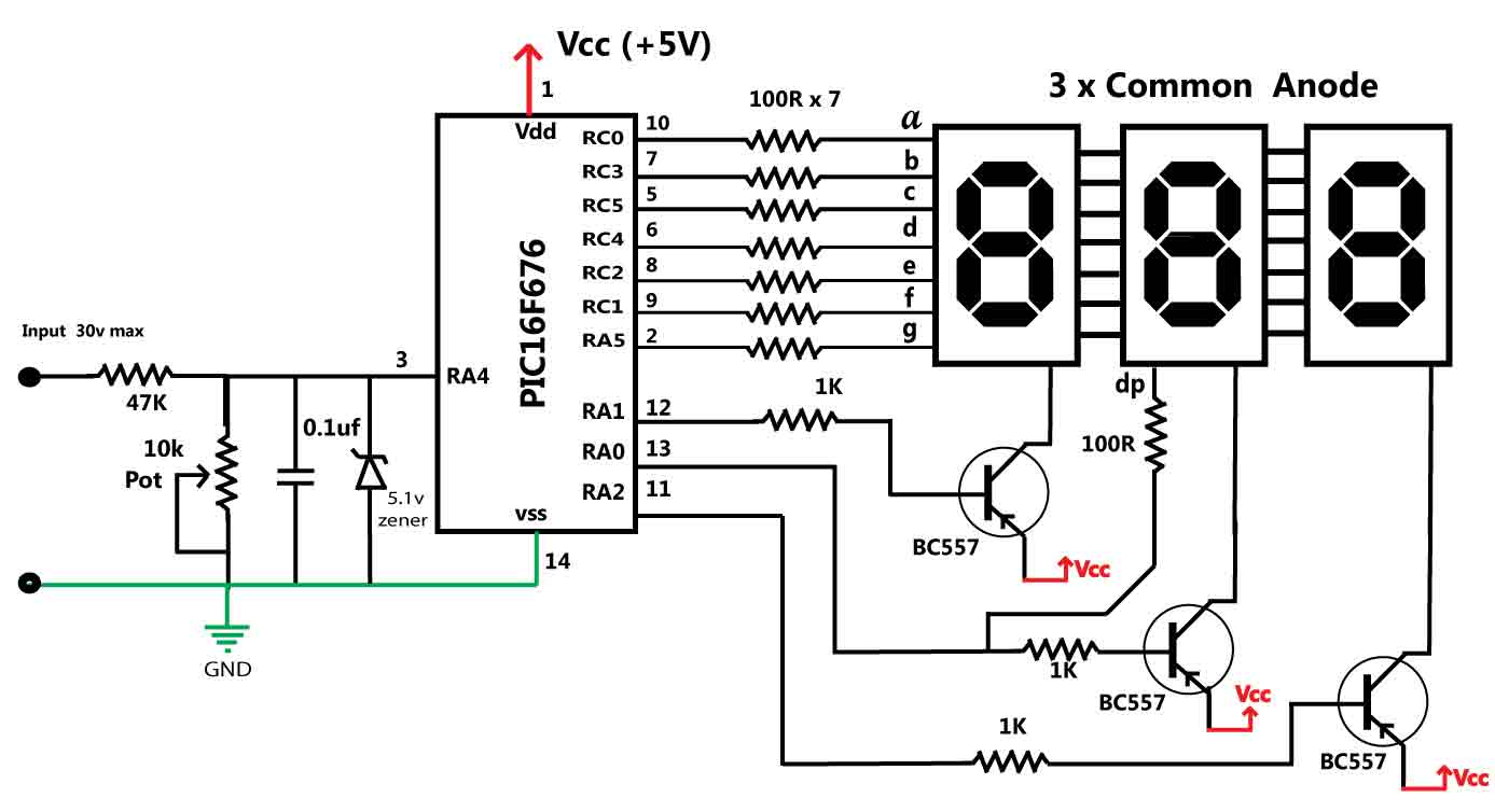
This is a simple 30V voltmeter utilizing the PIC16F676 microcontroller, which features a 10-bit analog-to-digital converter (ADC) and three common anode seven-segment LED displays. This circuit is designed to measure DC voltages up to 30V. Potential applications include use...
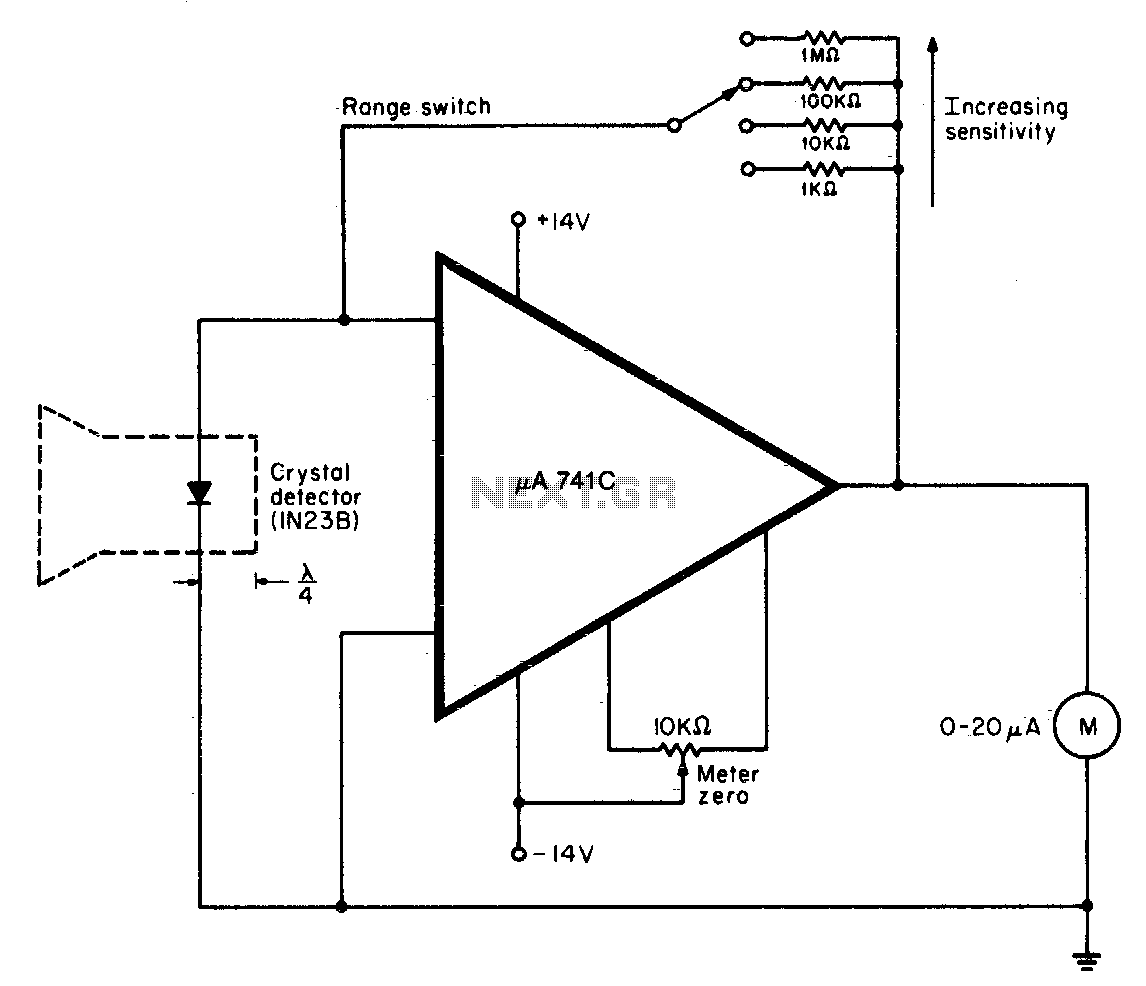
A waveguide directs energy onto a crystal detector during operation. The diode utilized is designed for X-band operation. The waveguide consists of a 1-inch piece of plastic tubing with flared ends. The plastic surface is treated with an electroless...
Any PIC microcontroller equipped with an ADC and sufficient memory to accommodate the program can be utilized. An LED is pulsed after each ADC acquisition to indicate the processor's activity, allowing for verification of software functionality. The LCD voltmeter...