
Frequency Meter / Frequency Counter 10Hz-60MHz

The 60MHz Frequency Meter/Counter is designed with precision and versatility in mind, making it an essential tool for engineers and technicians engaged in frequency analysis. The frequency measurement capability ranges from a low of 10Hz, suitable for low-frequency applications, to a maximum of 60MHz, accommodating a wide spectrum of electronic devices. The onboard amplifier enhances the sensitivity of the input stage, allowing the counter to detect even weak signals, which is particularly beneficial when working with crystal oscillators that may output minimal signal levels.
The integration of a TTL converter ensures compatibility with various digital circuits, facilitating seamless integration into existing electronic setups. The prescaler option is a significant feature that allows the user to extend the measurement range to 1GHz or more, making this device adaptable for high-frequency applications, such as RF circuit testing.
The user interface is simplified by the use of an LCD display, which provides clear and immediate feedback on the measured frequency. The detachable design of the LCD, connected through a 16-pin header, allows for convenient maintenance and replacement if necessary. Proper soldering of the headers is crucial for reliable operation, and the clear labeling of connections minimizes the risk of incorrect assembly.
The initialization sequence of the device, indicated by the "60 MHz Counter" message, confirms that the unit is powered and functioning correctly. The subsequent readiness to measure frequency is signaled by the display of "0.000000 MHz," ensuring that users can quickly ascertain the operational status. The inclusion of a trimpot for LCD contrast adjustment enhances usability, enabling users to optimize the display visibility under varying lighting conditions.
Overall, this frequency meter/counter stands out for its combination of stability, sensitivity, and user-friendly features, making it an invaluable asset in any electronic testing environment.60MHz Frequency Meter / Counter measures frequency from 10Hz to 60MHz with 10Hz resolution. It is extremely useful bench test equipment for testing and measuring frequency of oscillators, transmitters, radio receivers, function generators, crystals, etc. Counter provides exceptionally stable readings and has excellent input sensitivity thanks to o nboard amplifier and TTL converter. It can be even used for measuring weak signals from crystal oscillators. With the addition of simple prescaller it is possible to measure frequency up to 1GHz or more. Counter`s measuring range has now been extended form 50MHz up to 60MHz. LCD display is connected to PCB by 16-PIN male & female header and is easily detachable from the main board. 16-PIN Male Header must be soldered to LCD display. 16-PIN Female Header must be soldered to PCB. When counter is powered 60 MHz Counter message should be displayed on LCD display. A second after meter should be ready to measure the input frequency with 0. 000000 MHz being displayed on the display. If no text is visible adjust the LCD contract by trimming 10K trimpot counter-clockwise. 🔗 External reference
Related Circuits
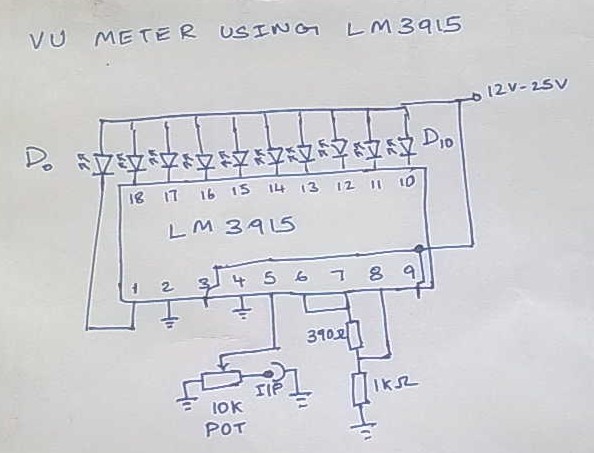
This is Version 1 of the VU meter that has been planned for construction. The final version will differ from the current one as its performance did not meet the requirements. This version cost approximately 100. The IC LM3915...
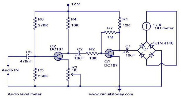
A simple audio level meter or Volume Unit (VU) level meter circuit with diagram and schematic. This sound level meter is designed using transistors with a flat frequency response in the range of 20Hz to 50kHz. The audio level meter...
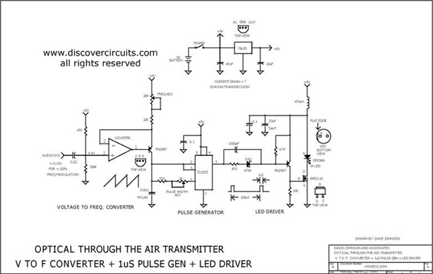
This circuit receives the signal from the amplifier and emits powerful 1μs infrared light pulses from a low-cost LED, which are frequency modulated by the audio information. The 10kHz center frequency of the pulse stream is sufficiently low, allowing...
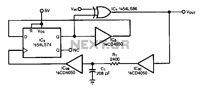
The circuit doubles the frequency of a digital signal by operating on both signal edges. Each transition causes the exclusive-OR gate IC1 to produce a pulse, which clocks flip-flop IC3 after propagating through buffers IC2C and IC2B. If capacitor...
The instrument used to measure battery capacity. The battery may be charged to any current in the range 0-3 A. The load current may be constant, may change over time or even break off completely. Unloading stops when the...
This circuit is a digital voltmeter diagram featuring an LED display. It is designed for measuring the output voltage of a DC power supply. The voltmeter incorporates a 3.5-digit LED display along with a negative voltage indicator. It is...