
Digital LED Voltmeter Using ICL7107

The digital voltmeter circuit operates primarily through the ICL7107 integrated circuit, which serves as the core of the measurement system. This chip is designed to convert the analog voltage input into a digital format that can be displayed on the LED screen. The ICL7107 features an internal reference voltage, which ensures accurate measurements across the specified range.
The circuit is structured to accept a DC input voltage, which is fed into the ICL7107. The input voltage is scaled down using a voltage divider network, if necessary, to ensure that it remains within the acceptable input range of the chip. This scaling is crucial for preventing damage to the ICL7107 and ensuring accurate readings. The negative voltage indicator is typically achieved through additional circuitry that can detect and display negative voltages, enhancing the versatility of the voltmeter.
The LED display consists of 3.5 digits, allowing for clear visual representation of the measured voltage. The design is optimized for low power consumption, with the entire circuit operating on a 5V supply and drawing only about 25mA. This makes it suitable for portable applications or systems where power efficiency is a priority.
The compact size of the printed circuit board, measuring 3cm x 7cm, allows for easy integration into various electronic projects or devices. The layout of the PCB must be carefully considered to minimize noise and interference, which could affect the accuracy of the voltage measurements. Proper grounding and routing techniques are essential in the design of the PCB to ensure reliable operation.
Overall, this digital voltmeter circuit is an efficient and effective solution for measuring DC voltage, with a user-friendly interface and a compact form factor, making it suitable for a wide range of applications in electronic testing and development.This circuit is a circuit diagram digital voltmeter with LED display. It`s ideal to use for measuring the output voltage of your DC power supply. It includes a 3.5-digit LED display with a negative voltage indicator. It measures DC voltages from 0 to 199.9V with a resolution of 0.1V. The voltmeter is based on single ICL7107 chip and may be fitted on a small 3cm x 7cm printed circuit board. The circuit should be supplied with a 5V voltage supply and consumes only around 25mA 🔗 External reference
Related Circuits
This circuit diagram represents a radio-controlled system, commonly used in toy car applications for children. The circuit consists of two main parts: the transmitter and the receiver. The transmitter generates radio signals using an oscillator circuit formed by transistor...

This is a circuit design for a digital voltmeter with an LED display. It is suitable for measuring the output voltage of a DC power supply. The circuit features a 3.5-digit LED display with a negative voltage indicator and...
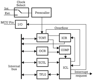
Although there are significant variations between different implementations of the general-purpose timer in various microcontrollers, many similarities exist in the principles of operation and the structure of the timer subsystem. The central element of the timer subsystem is a...
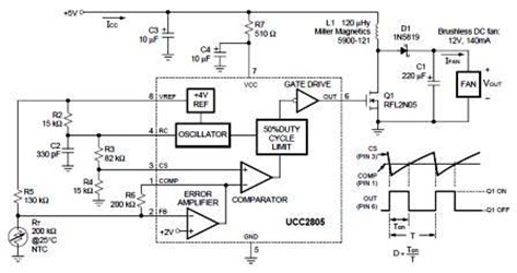
A temperature-controlled pulse-width-modulator (PWM) boost converter circuit diagram is illustrated in the following figure. This boost converter is designed to operate a 12V fan using a 5V supply while maintaining temperature control. The temperature-controlled PWM boost converter circuit operates by...
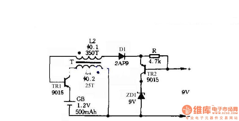
The circuit does not require a separate power switch or transformation to control the switches on the table. It offers advantages such as low power consumption, stability, reliability, and no impact on instrument accuracy. The transformer T in the...
This circuit uses two quad op-amps to form an eight LED audio level meter. The op-amp used in this particular circuit is the LM324. It is a popular IC and should be available from many parts stores. More: The...