
3 Digits Digital Volt Meter with PIC16F676

The circuit design for the 3-digit digital voltmeter involves several key components working in unison to accurately measure and display voltage levels. The core of this circuit is the PIC16F676 microcontroller, which is programmed to convert the analog voltage input into a digital format suitable for display.
The analog voltage signals are fed into one of the analog-to-digital converter (ADC) channels of the PIC16F676. The ADC converts the incoming analog voltage to a digital value, which the microcontroller processes. The resolution of the ADC in this microcontroller is 10 bits, allowing for accurate measurement of voltages within a specified range.
The 3-digit 7-segment display consists of three individual 7-segment modules, each capable of displaying numbers from 0 to 9. The microcontroller controls these segments by sending the appropriate signals to illuminate the required segments based on the processed digital value. The display is refreshed at a sufficient rate to ensure that the readings appear stable and readable.
In addition to measuring voltage, the circuit can be adapted to measure DC current. This is achieved by incorporating a shunt resistor in parallel with the load. The voltage drop across this resistor, which is proportional to the current flowing through it, can be measured using the same ADC channel. The microcontroller can then calculate the current based on the known value of the shunt resistor and display it on the same 7-segment display.
Powering the circuit typically requires a stable voltage source, which can be achieved using a battery or a regulated power supply. Additional components such as capacitors may be included for filtering purposes to minimize noise in the analog signal, ensuring more accurate readings.
Overall, this digital voltmeter design exemplifies the integration of microcontroller technology into measurement applications, providing a compact and efficient solution for voltage and current monitoring.This is simple 3-digits digital volt meter.PIC16F676 used to read analog signal(voltage) and display the value on 3-digits 7-segment. You can apply similar principles to measure DC current with parallel R shunt 🔗 External reference
Related Circuits
A phase-locked loop (PLL) is widely utilized in telecommunications, control systems, and various other electronic applications. PLLs can be employed to demodulate frequency-modulated (FM) signals and generate a stable output frequency. A phase-locked loop is an essential feedback control system...
This transmitters' intended purpose is for morse-code only in the 30 meter band (10Mhz). It is a low-power QRP type and needs to be connected to your existing tranceiver. The harmonic rejections on the prototype were measured at 40dB...
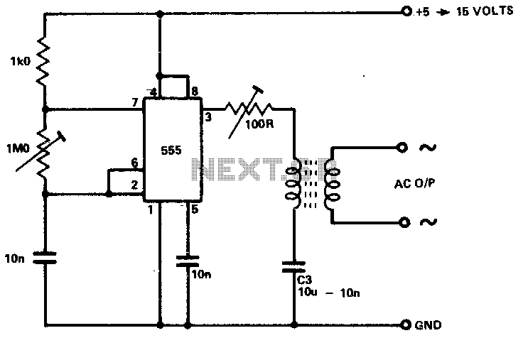
The circuit is designed to supply power for portable Geiger counters, dosimeter chargers, high resistance meters, and similar devices. The 555 timer integrated circuit (IC) operates in its multivibrator mode, with the frequency adjusted to optimize the characteristics of...
A tachometer can be constructed using the TC9400 in frequency-to-voltage (F/V) mode to convert frequency information (RPM) into a linearly proportional voltage. This voltage can then be compared to one of several comparators (in this example, using eight). The...
If the instruments have power when the key is turned on, the next step is to check the neutral safety switch. According to standard boat wiring colors, follow the yellow/red wire from the starter post on the key switch...

The following circuit diagram of a dual voltage power supply can be used for miscellaneous applications. It requires a few components to build. The most important components of this circuit are regulators: 1: (AN) 7812 and 2: (AN) 7912....