
Frequency to voltage converter using LM331

The LM331 integrated circuit operates based on the principle of converting frequency signals into corresponding voltage levels, making it a versatile component in various electronic systems. The architecture of the circuit typically includes several key components: a capacitor (C3) that differentiates the input frequency signal, a resistor (R7) that helps shape the pulse train, and the timing components (R1 and C1) that define the response characteristics of the circuit.
When the input frequency signal is applied, the capacitor (C3) serves to differentiate the signal, producing a pulse train that represents the changes in the frequency over time. This pulse train is then directed to pin 6 of the LM331, where the threshold comparator monitors the signal. The negative edges of the pulse train trigger the internal comparator, which activates the timer circuit within the IC.
The output current from pin 6 of the LM331 is directly influenced by the input frequency and the timing components. As the input frequency increases, the current output also increases proportionally, thereby generating a corresponding output voltage (Vout) across the load resistor (R4). This output voltage can be utilized in various applications, such as analog-to-digital conversion systems, where it can be further processed or displayed.
In summary, the LM331 serves as a precise and efficient means of converting frequency signals into linear voltage outputs, making it an essential component in modern electronic design and applications. Its ability to maintain excellent linearity and wide dynamic range enhances its usability in various measurement and control systems.LM331 is basically a precision voltage to frequency converter from National Semiconductors. The IC has a hand full of applications like analog to digital conversion, long term integration, voltage to frequency conversion, frequency to voltage conversion. Wide dynamic range and excellent linearity makes the IC well suitable for the applications men tioned above. Here the LM331 is wired as a frequency to voltage converter which converts the input frequency into a proportional voltage which is extremely linear to the input frequency. The frequency to voltage conversion is attained by differentiating the input frequency using capacitor C3 and resistor R7 and feeding the resultant pulse train to the pin6 (threshold) of the IC.
The negative going edge of the resultant pulse train at pin6 makes the built-in comparator circuit to trigger the timer circuit. At any instant, the current flowing out of the current output pin (pin 6) will be proportional to the input frequency and value of the timing components (R1 and C1).
As a result a voltage (Vout) proportional to the input frequency (Fin) will be available across the load resistor R4. 🔗 External reference
Related Circuits
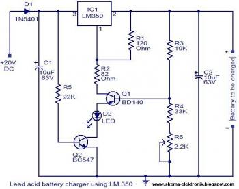
The circuit is designed as a constant voltage source with a negative temperature coefficient. The transistor Q1 (BD 140) serves as the temperature sensor, while transistor Q2 prevents battery discharge through resistor R1 when mains power is unavailable. The...

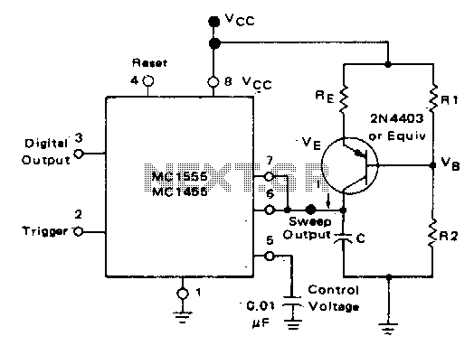
The difference between instantaneous frequency and central frequency of the carrier is directly proportional to the instantaneous value of the amplitude of the message signal. A 555 Timer configured in Astable Mode can be utilized for generating Frequency Modulated...

Consider a capacitor with capacitance C that charges to a voltage V and discharges to 0V at a frequency of 5 times per second. To estimate the average current, also referred to as the RMS current, a rough approximation...
If you have ever wanted a high-voltage generator to create impressive lightning effects, conduct Kirlian photography experiments, or experiment with neon lights, this project is ideal. It describes a laboratory pulse generator utilizing an auto-ignition coil, capable of delivering...
In the monostable mode, the resistor can be replaced by a constant current source to provide a linear ramp voltage. The capacitor still charges from 0 to 2/3 Vcc. In a monostable multivibrator configuration, the circuit typically consists of a...
An LED flasher circuit can be constructed using a 555 integrated circuit (IC). The use of the 555 IC allows for greater flexibility in adjusting the flashing rate of the LED. This LED flasher circuit is similar to other...