
Low-Cost Logarithmic Converter Using Opamp and Transistor

The logarithmic converter circuit is designed to convert linear input signals into logarithmic output signals, which is useful in various applications such as audio signal processing, sensor signal conditioning, and data acquisition systems. The Motorola MC1539G op-amp serves as the core component for signal amplification and processing. This op-amp features low noise and high gain, making it suitable for precision applications.
In this configuration, the op-amp is set up in a non-inverting mode to amplify the input signal. The output of the op-amp is then fed to a PNP transistor, which operates in the active region to provide the logarithmic response. The transistor's base is connected to the op-amp output, while the emitter is linked to the ground through a resistor. This configuration allows the circuit to produce a voltage output that is proportional to the logarithm of the input current, effectively compressing the dynamic range of the input signal.
Additional passive components such as resistors and capacitors may be included in the circuit to stabilize the op-amp, set the gain, and filter noise. The choice of these components will influence the performance characteristics of the logarithmic converter, including bandwidth, linearity, and temperature stability. Proper selection and arrangement of these components are essential to ensure that the circuit meets the desired specifications for its intended application.
Overall, this low-cost logarithmic converter circuit demonstrates an effective use of op-amp and transistor technology to achieve logarithmic signal processing, making it a valuable tool in electronic design and signal conditioning.This low-cost logarithmic converter is built using op-amp and transistor. This circuit uses a Motorola MC1539G op-amp which is connected to PNP transistor. To.. 🔗 External reference
Related Circuits
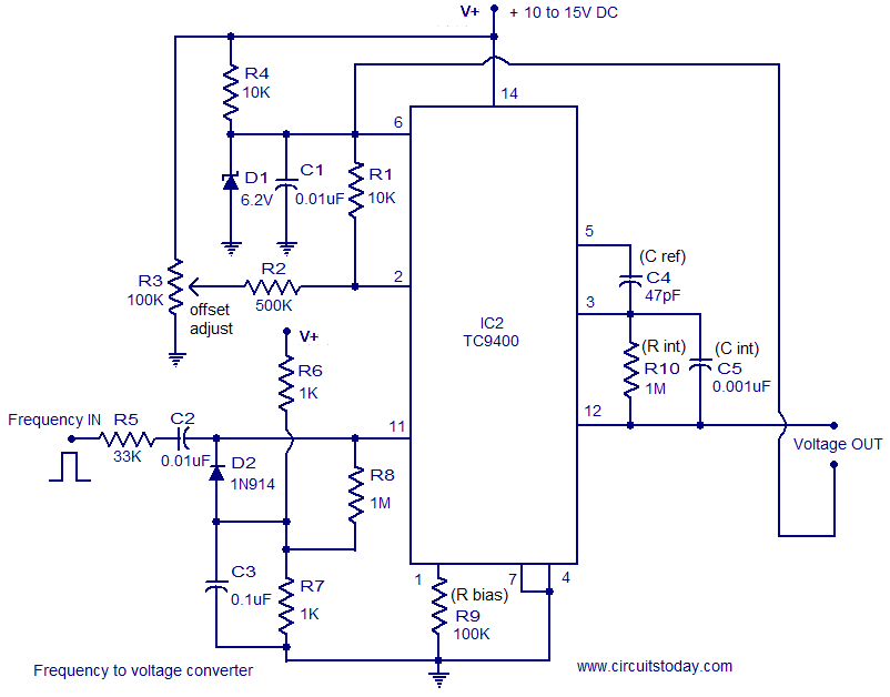
A simple and low-cost frequency-to-voltage converter based on the TC9400 IC from Microchip is presented. The TC9400 can be configured as either a voltage-to-frequency converter or a frequency-to-voltage converter, requiring minimal external components. The internal functional blocks of the...
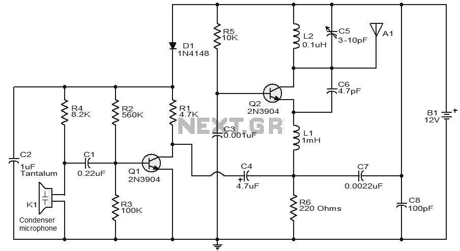
This circuit features a very stable and simple FM transmitter design. This transmitter can achieve a range of approximately 200 meters when properly matched. The FM transmitter circuit typically consists of several key components: an oscillator, modulator, amplifier, and antenna....
This circuit is a conventional Pierce type oscillator that utilizes a JFET. It employs fundamental mode crystals and demonstrates decent performance and reliability. The Pierce oscillator is a popular configuration for generating stable oscillations, particularly in applications requiring a stable...
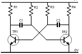
Assume one of the transistors, TR1, becomes conductive initially. Under this condition, the collector-emitter voltage of TR1 should ideally be zero; however, it will be approximately 0.1 volts, while the base-emitter voltage is +0.6 volts. As a result, capacitor...
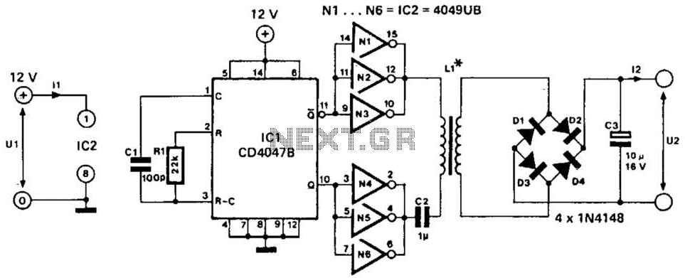
A DC-to-DC step-up converter is typically implemented using a transformer, which converts DC voltage to AC voltage, steps it up with the transformer, and then rectifies and filters the output to achieve a higher DC voltage. However, a voltage...
This low-power converter supplies approximately 100 mW of DC power to a load and is useful for isolating or deriving DC voltages. It operates at a frequency of around 200 kHz. The inductor is wound on a 22-mm diameter,...