
Voltage-to-Pulse Duration Converter

The Voltage-to-Pulse Duration Converter circuit utilizes a timer IC, typically the 555 timer, configured in monostable mode. In this configuration, the timer generates a pulse of a specified duration in response to a triggering voltage input. The duration of the output pulse is determined by the resistor and capacitor values connected to the timer.
An operational amplifier is employed to condition the input voltage signal. The OP Amp can be configured as a comparator to compare the input voltage against a reference voltage. When the input voltage exceeds the reference level, the OP Amp output triggers the timer IC, initiating the pulse generation.
In designing the circuit, it is essential to select appropriate resistor and capacitor values to achieve the desired pulse duration. The relationship between the pulse width (T) and the RC network can be described by the formula T = 1.1 * R * C, where R is the resistance in ohms and C is the capacitance in farads.
The operational amplifier's gain settings may also need adjustment to ensure proper triggering of the timer IC. Additionally, power supply considerations are critical, as both the OP Amp and timer IC require stable voltage levels for accurate operation.
Overall, this circuit is useful in applications where voltage levels need to be translated into time-based signals, such as in digital communication systems or pulse-width modulation (PWM) applications.This is a circuit of Voltage-to-Pulse Duration Converter. This circuit is used to convert voltage into pulse duration by combining a timer IC and an OP Amp 🔗 External reference
Related Circuits
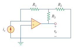
At a T connection, the connections are clear, but at a cross, the connections are not clear, especially if there are no junction dots elsewhere in the schematic. It appears that the bottom of the I and the right...
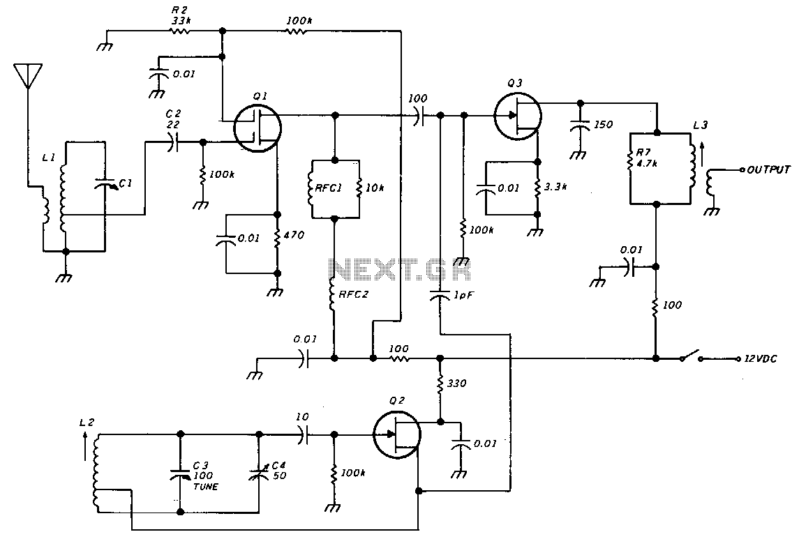
The unit consists of an RF amplifier Q1, a local oscillator Q2, and a mixer Q3. The two frequency bands are covered without a band switch by utilizing an intermediate frequency (IF) of 3.5 MHz. The oscillator operates within...
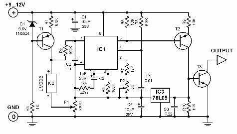
While conducting background research on the Philips I2C bus, an application note authored by Herman Schutte from Philips Semiconductors Systems Laboratory in Eindhoven was discovered. Mr. Schutte detailed an efficient method for interfacing sections of the I2C bus operating...
In certain temperature measurement applications, converting the measured value into a frequency rather than a voltage offers distinct advantages. A temperature-to-frequency converter can be directly interfaced with a frequency counter or connected to a computer without necessitating an A/D...
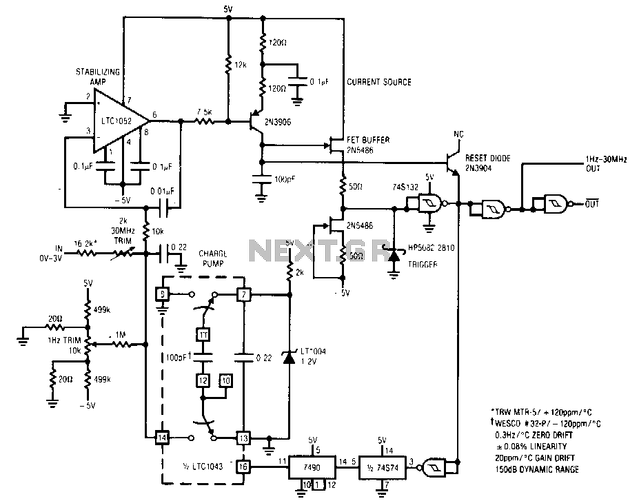
The circuit features a 1 Hz to 30 MHz output with a dynamic range of 150 dB, designed for a 0 to 5 V input. It exhibits a linearity of 0.08% across its entire 71/3 decade range, with a...
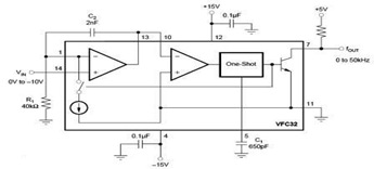
The circuit diagram of a voltage-to-frequency (V/F) converter is presented, designed to handle negative input voltage. It employs the VFC32 voltage-to-frequency converter, which is commonly utilized in various applications. The V/F converter circuit is essential in converting an analog voltage...