fridge door alarm circuit
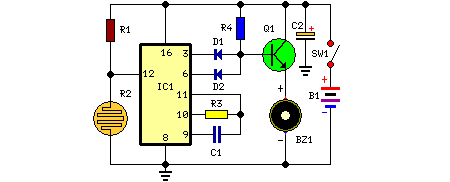
This circuit is housed in a compact enclosure and is positioned within the refrigerator, either near the lamp or at the door opening. When the refrigerator door is closed, the interior remains dark, causing the photoresistor R2 to exhibit a high resistance (up to 200K ohms). This high resistance keeps pin 12 of IC1 in a high state, preventing any counting operation. When light enters through the opening or the refrigerator lamp is turned on, the photoresistor’s resistance drops significantly (to less than 2K ohms), resulting in a low signal at pin 12. This triggers IC1 to begin counting. After a preset delay of 20 seconds, the piezo sounder emits a beep for 20 seconds, followed by a pause of the same duration. This beeping cycle continues until the refrigerator door is closed. Additionally, diode D2, connected to pin 6 of IC1, facilitates the piezo sounder to beep at a rate of three times per second.
The circuit utilizes a photoresistor (R2) to detect ambient light levels within the refrigerator. When the door is closed, the absence of light leads to a high resistance state, effectively disabling the timer function of the integrated circuit (IC1). The photoresistor is a critical component that responds to light changes, allowing the circuit to differentiate between open and closed door states.
Upon exposure to light, R2's resistance drops, allowing current to flow and pulling pin 12 of IC1 low. This transition initiates a timing sequence controlled by IC1, which is likely a timer IC such as the 555 timer in monostable mode. The preset delay is set to 20 seconds, indicating that the circuit is designed to provide a warning signal if the door remains open for an extended period, potentially to prevent food spoilage due to temperature rise.
The piezo sounder, a key output component, is activated by IC1 after the delay, producing an audible beep. This sound serves as an alert to the user that the refrigerator door has been left ajar. The sound duration is also set to 20 seconds, followed by a silence period of the same length, creating a repetitive alert system. The inclusion of diode D2 ensures that the beeping occurs at a consistent rate of three beeps per second, enhancing the alert's effectiveness.
This circuit design is particularly useful in household refrigerators, where it can help maintain food safety by alerting users to an open door. The simplicity of the design, using common components like a photoresistor, timer IC, and piezo sounder, makes it easy to implement and cost-effective. Additionally, the compact form factor allows for easy installation within the refrigerator without occupying significant space.This circuit, enclosed into a small box, is placed in the fridge near the lamp (if any) or the opening. With the door closed the interior of the fridge is in the dark, the photo resistor R2 presents a high resistance (up to 200K) thus clamping IC1 by holding pin 12 high.
When a beam of light enters from the opening, or the fridge lamp illuminates, the photo resistor lowers its resistance (less 2K), pin 12 goes low, IC1 starts counting and, after a preset delay (20 seconds in this case) the piezo sounder beeps for 20 sec. then stops for the same lapse of time and the cycle repeats until the fridge door closes. D2 connected to pin 6 of IC1 allows the piezo sounder beeping 3 times per second.. 🔗 External reference
