
fully automatic emergency light

The charging circuit described integrates both an inverter and a charger, functioning effectively to manage battery charging while providing illumination during power outages. The NE555 timer, configured as an astable multivibrator, produces a stable square wave that drives a Darlington pair, enabling efficient operation of the tube light. The transformer design is critical for ensuring proper voltage and current characteristics, with specific winding ratios to achieve the desired output. The inclusion of filtering capacitors enhances the reliability of the power supply by minimizing ripple, thus ensuring that the LM317 regulator can provide a stable charging voltage. The use of a zener diode for voltage regulation prevents overcharging, safeguarding the battery's longevity and performance. Overall, the circuit design emphasizes safety, efficiency, and functionality, making it suitable for emergency lighting applications.The charging circuit stops automatically when the battery is fully charged. So you can leave the emergency light connected to AC mains overnight without any fear. The circuit can be divided into inverter and charger sections. The inverter section is built around timer NE555, while the charger section is built around 3-terminal adjustable regulator LM317. In the inverter section, NE555 is wired as an astable multivibrator that produces a 15kHz squarewave. Output pin 3 of IC 555 is connected to the Darlington pair formed by transistors SL100 (T1) and 2N3055 (T2) via resistor R4.
The Darlington pair drives ferrite transformer X1 to light up the tubelight. For fabricating inverter transformer X1, use two EE ferrite cores (of 25G—13G—8mm size each) along with plastic former. Wind 10 turns of 22 SWG on primary and 500 turns of 34 SWG wire on secondary using some insulation between the primary and secondary.
To connect the tube-light to ferrite transformer X1, first short both terminals of each side of the tube-light and then connect to the secondary of X1. (You can also use a Darlington pair of transistors BC547 and 2N6292 for a 6W tube-light with the same transformer.
) When mains power is available, reset pin 4 of IC 555 is grounded via transistor T4. Thus, IC1 (NE555) does not produce square-wave and emergency light turns off in the presence of mains supply. When mains fails, transistor T4 does not conduct and reset pin 4 gets positive supply though resistor R3.
IC1(NE555) starts producing square wave and tube-light turns on via ferrite transformer X1. In the charger section, input AC mains is stepped down by transformer X2 to deliver 9V-0-9V AC at 500mA. Diodes D1 and D2 rectify the output of the transformer. Capacitors C3 and C4 act as filters to eliminate ripples. The unregulated DC voltage is fed to IC LM317 (IC2). By adjusting preset VR1, the output voltage can be adjusted to deliver the charging voltage. When the battery gets charged above 6. 8V, zener diode ZD1 conducts and regulator IC2 stops delivering the charging voltage. Assemble the circuit on a general-purpose PCB and enclose in a cabinet with enough space for the battery and switches.
Connect a 230V AC power plug to feed charging voltage to the battery and make a 20W tube outlet in the cabinet to switch on the tube-light. Source: 🔗 External reference
Related Circuits
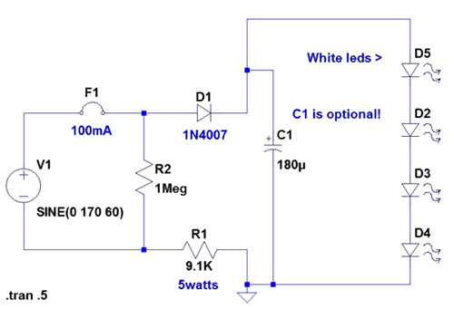
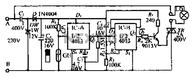
If the AC supply is 220 volts, which resistor should be replaced and with which one? Since 220V is twice that of 110V, the resistance value needs to be doubled accordingly. It is suggested to replace the 9.1kΩ resistor...
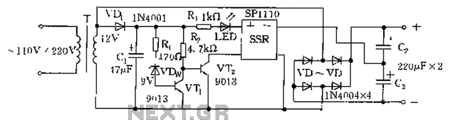
The circuit is automatically converted to a low-voltage configuration. A 220V AC supply is stepped down by transformer T. After this, the breakdown voltage of diode VDw causes transistors VT1 and VT2 to turn off, resulting in the solid-state...
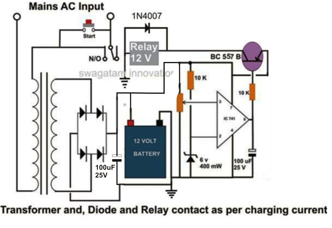
This design is intended for charging high-capacity lead-acid batteries in the range of 100 to 200 Ah. The system operates automatically, disconnecting power from both the battery and itself once the battery is fully charged. For simplicity, a filter...
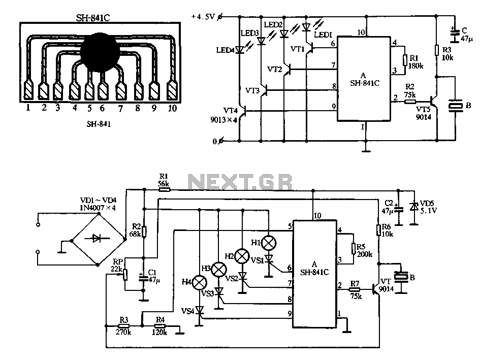
Figure 2-78 illustrates the SH-841 as the central component in a holiday lights controller. It utilizes SCRs VS1 to VS4 to drive light strings H1 to H4, causing them to flash. The operating voltage is sourced from AC through...
An intriguing lighting solution for bicycles, utilizing LEDs. It features low power consumption and includes a circuit diagram for an electronics project, operating at 9V, utilizing the NE555 timer. The bicycle lighting circuit employs a NE555 timer IC configured in...
Purchase a 1W white LED and utilize a mobile phone battery to create a small lamp. A lampshade can be made from a glass-like milky white plastic bottle. The LED emits light through a radiating plate, which has two...