
SH-841 ASIC holiday lights

The circuit design described in Figure 2-78 serves as an effective holiday lights controller, integrating both visual and auditory effects. The SH-841 microcontroller is the heart of the system, managing the operation of the light strings. The SCRs (Silicon Controlled Rectifiers) VS1 to VS4 are crucial for controlling the flow of current to the light strings H1 to H4. These SCRs allow for the modulation of the light output, creating a flashing effect synchronized with a music signal.
The AC power supply is converted to a usable DC voltage through the bridge rectifier composed of diodes VD1 to VD4. This configuration ensures that the circuit can handle both halves of the AC waveform, providing a smooth DC output. Resistor R1 is used to step down the voltage to a safe level for the subsequent components. Diode VD5, in conjunction with capacitor C2, serves to filter out any ripple from the rectified voltage, ensuring a stable DC supply for the circuit's operation.
The audio component of the circuit is facilitated by the amplifying transistor VT, which boosts the music signal output. This amplified signal is then used to drive a piezoelectric ceramic sheet B, which converts the electrical signal into sound. The integration of sound with the visual elements of the holiday lights enhances the overall experience. The potentiometer RP provides user-adjustable control over the sound volume, allowing for customization based on user preference or ambient conditions.
Overall, the circuit exemplifies a well-designed integration of lighting and sound, suitable for festive decorations and events. The combination of SCRs for light control and a transistor for sound amplification showcases a practical application of electronic components in creating an engaging user experience.Figure 2-78 is SH-841 as the core device made holiday lights controller. By SCR VSl ~ VS4 to drive light string H1 ~ H4 flashes. Manifold operating voltage by AC by VD1-VD4 bri dge rectifier, Rl buck, VD5 filter regulator and C2 obtained. Manifold 2 feet of the music signal output by the amplifying transistor VT to drive the piezoelectric ceramic sheet B made sound. Adjustment potentiometer RP can control the sound volume.
Related Circuits
The brightness of a fluorescent light bulb or neon tube is not as easily adjustable as that of an incandescent bulb because it requires a much higher voltage to start. Once initiated, it operates at the electrical network voltage....

This circuit replicates the starting light sequence used by FISA in Formula One racing. It can be utilized with slot car sets (such as HO scale AFX, Life Like, or Tyco sets) or radio-controlled cars. The circuit employs a...
A 2001 Monte Carlo is experiencing electrical issues where only the lights are functioning. The radio, wipers, turn signals, and dash lights do not operate when the ignition key is turned. It has been suggested that the computer system...
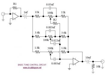
The following diagram illustrates the schematic of an Active Tone Control circuit, commonly referred to as "ACTOR." The ACTOR is an electronic audio circuit designed to enhance loudness by adjusting bass and treble audio signals. It operates using the...

This circuit simulates the flashing lights of a police car, similar to those seen on British police vehicles. The operational amplifier IC1a functions as a square wave oscillator, with an adjustable frequency controlled by the variable resistor VR1 to...
A series of shunts and multipliers selected by a switch can be utilized in conjunction with a single basic meter to create a multirange instrument, commonly referred to as a multimeter. This device is capable of measuring voltage, current,...