
7 Segment Display Counter based 74LS90

The 7-segment counter circuit employing the 74LS90 TTL IC functions as a decade counter, capable of counting from 0 to 9. The 74LS90 is a synchronous counter that features four output pins (Q0 to Q3), which represent the binary count. These output pins can be connected to a 7-segment display decoder, such as the 74LS47, which converts the binary output into a format suitable for driving a 7-segment display.
The circuit operates by receiving a TTL-compatible clock signal, which increments the counter with each pulse. The counter's output can be directly connected to a 7-segment display through the 74LS47 decoder. The 74LS47 takes the binary-coded decimal (BCD) input from the 74LS90 and activates the appropriate segments of the display to represent the decimal digits from 0 to 9.
For expansion, additional 74LS90 and 74LS47 pairs can be connected in cascade. The Q3 output of the first 74LS90 can be linked to the clock input of the next 74LS90, allowing for seamless counting beyond a single digit. The connection between pins 11 and 6 of the 74LS90 and pin 14 of the subsequent 74LS90 serves as an interconnection point for cascading multiple counters. This configuration permits the construction of counters with multiple digits, enabling displays of larger numerical values.
Power supply considerations for the circuit include ensuring that the ICs are powered with a stable voltage, typically +5V for TTL logic. Additionally, decoupling capacitors should be placed near the power supply pins of the ICs to filter out noise and stabilize the voltage supply.
Overall, the 7-segment counter circuit based on the 74LS90 TTL IC provides a versatile and expandable solution for displaying numerical counts in various electronic applications. Its straightforward design and compatibility with TTL logic make it an attractive choice for both educational and practical implementations in electronic projects.Here is a 7 segment counter circuit based on IC 74LS90 TTL. This can be used in conjunction with several circuits where a counter to show the progress adds a little more attractive. This circuit accepts any TTL compatible logic signal, and can be extended easily. You can add more digits by building a second (or third, or fourth, etc. ) circuit and c onnecting the pin 11-6 junction of the 74LS90 and 74LS47 to pin 14 of the 74LS90 in the other circuit. You can keep expanding this way to as many digits as you want. 🔗 External reference
Related Circuits
The objective of this project is to create a controller-based model that counts the number of individuals entering a specific room and activates the lighting accordingly. This is achieved through the use of sensors that detect the current number...
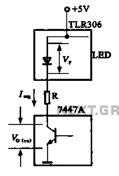
The circuit depicted is a large high-brightness LED driver designed to provide sufficient drive current, utilizing integrated circuits such as the 7447A or 74247. The digital display tube consists of eight light-emitting diodes, with seven dedicated to the digital...
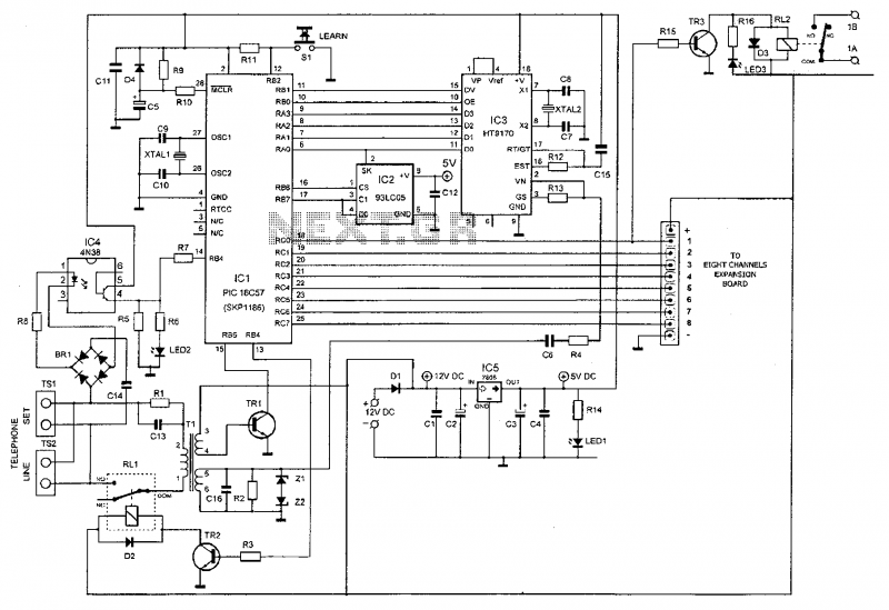
This device enables remote control of various appliances (up to eight with suitable add-on expansion boards) such as lights, water heaters, air conditioning, plant watering systems, alarms, etc., via a relay. It allows users to perform actions such as...
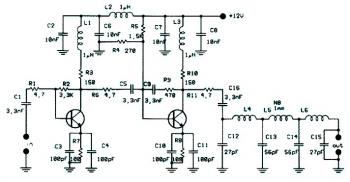
This circuit diagram illustrates a linear FM booster and RF amplifier utilizing the Philips 2N4427 transistor. The RF amplifier is designed to enhance the performance of small FM transmitters and bugs, employing two Philips 2N4427 transistors, delivering approximately 1...
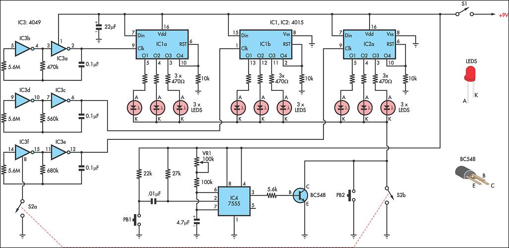
This circuit is designed as a toy to help young children learn to count. The power is activated by switch S1, and then switch S2 is closed, causing nine LEDs to flash slowly. When S2 is opened, the LEDs...
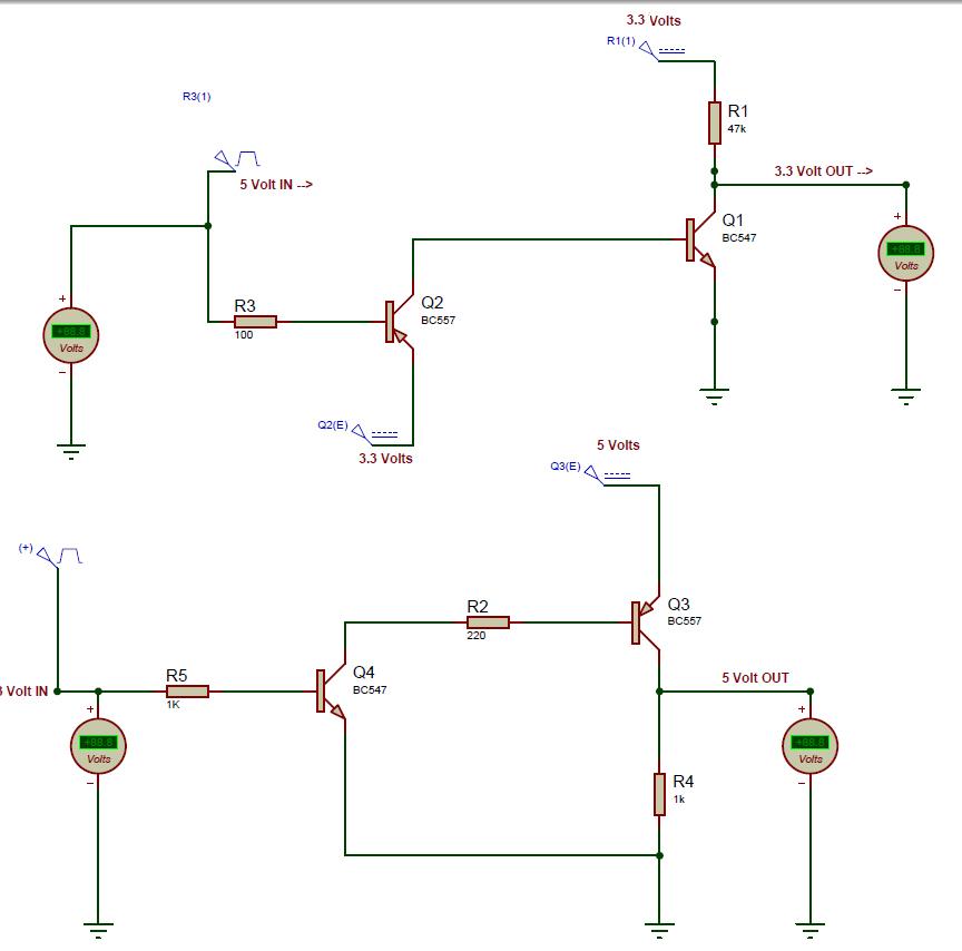
Most devices currently operate at 3.3 volts, and their communication levels also function at this voltage. For instance, the XBee module operates at 3.3 volts, but to interface it with microcontrollers that operate at 5 volts, it is necessary...