
Fun with Filters!
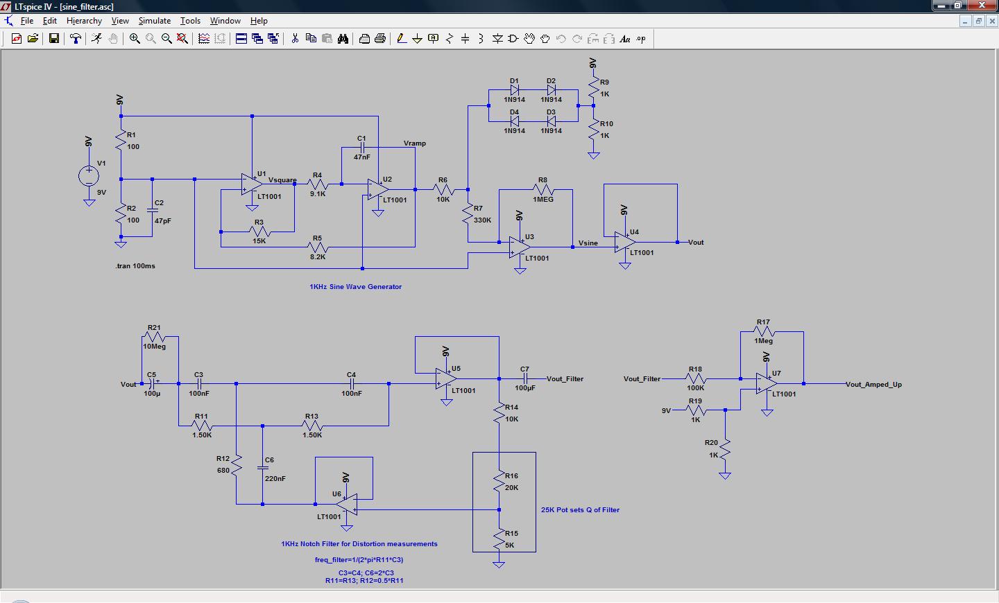
A comprehensive circuit schematic for the sine wave generator and notch filter can be constructed using operational amplifiers configured in an inverting or non-inverting arrangement to generate the desired sine wave output. The sine wave generator typically employs an integrator to shape a triangle wave and then a comparator to convert this triangle wave into a sine wave. The operational amplifiers should be selected based on their bandwidth and slew rate to ensure they can accurately produce the 1 kHz sine wave.
The notch filter can be designed using a band-stop configuration that includes resistors, capacitors, and operational amplifiers to create a filter that effectively attenuates signals at 1 kHz while allowing other frequencies to pass. The design parameters, such as resistor and capacitor values, should be calculated to achieve a quality factor (Q) that provides sufficient attenuation at the fundamental frequency without significantly affecting the harmonic content.
The performance of the notch filter can be evaluated through frequency response analysis, which can be conducted using simulation software like LTSPICE or through physical testing with a function generator and oscilloscope. The use of a distortion analyzer, such as the HP 331A, allows for precise measurement of the total harmonic distortion, providing insight into the effectiveness of the notch filter and the overall quality of the sine wave generated. The results from both simulation and physical testing can be compared to assess the accuracy of the circuit design and implementation.
Overall, this project illustrates the importance of analyzing and refining signal quality in electronic circuits, particularly in applications where sine wave purity is critical, such as in signal processing and communications.I built a simple 1KHz 6Vpp Sine Wave Generator from a handful of opamps and passives I had laying around. You can check out that project here. I thought it would be fun to quantify just how good of a Sine Wave this circuit was; after all it was just a wave-shaped triangle wave, so I wasn`t expecting too much.
But if I quantify h ow good of a sine wave it is I can tweak the circuit to try and make if better. Essentially, a perfect sine wave should only have a single frequency component at the fundamental frequency, but real sine waves have harmonic distortion. This harmonic distortion is the part of the sine wave that we really don`t want; a poor sine wave has lots of harmonic content and a good sine wave has little to no harmonic content.
So if we measure the amplitude of the harmonics we can quantify how good our sine wave is! What we need to do is design a Notch filter at 1KHz. This will remove the fundamental frequency and leave the Harmonic content. Below is an LTSPICE schematic of Sine Wave Generator and Notch Filter. When the 1KHz signal is passed through the 1KHz centered notch filter the fundemental frequency is removed and what is left is the Harmonic content. You can see the 3rd harmonic at ~3KHz is what is left. Below is the FFT of the input Sine Wave and the Output of the Notch Filter; you can see the fundamental frequency amplitude is lower with minimal effect on the harmonic content.
Now that I had a base line simulation working I grabbed my soldering iron and built up the 1KHz Notch Filter dead bug style in an Altoids box. I wish I had a Network Analyzer or at minimum a Spectrum Analyzer with a tracking output to measure my filters frequency response, but all I had was a function generator and a scope.
I swept the function generator`s output frequency from 10Hz to 100KHz and could see that my filter worked well at filtering out 1KHz signals. I wanted a second opinion, so I grabbed a HP 331A Distortion Analyzer and set it up. I hadn`t used one of these since I interned at an RF Radio Manufacturer back in 2002. I used it to measure receiver sensitivity performance. I had to dig up a manual to remember how to setup the HP 331A. It is a bit confusing because you have to setup the meter to 100% full scale based on your input, then adjust the frequency & balance adjustments until you get the lowest % THD reading.
I monitored the Output of the 331A with a scope to see that I had fully removed the 1KHz fundamental and all that was left was a dirty looking 3KHz waveform (3rd harmonic). The HP 331A measured a THD of 7. 4%; pretty close to my homemade notch filter 6% reading. It makes sense that my filter`s THD measurement would be lower, because it probably attenuated the 3rd harmonic a bit more than the much more precise HP 331A`s notch filter would do.
Both filters did a nice job removing the fundamental and the 3rd harmonic is defiantly the most dominate remaining frequency. This was a fun project and cool to see that my Notch Filter implementation`s THD readings weren`t that far off from a HP331A`s measurements.
I thought I would do one last test to see the performance of the Notch Filter on a much cleaner sine wave. I used a BK Precision 3011B to generate an identical (but much cleaner) 1KHz 6Vp-p Sine Wave and used the Notch Filter to measure its THD.
🔗 External reference
Related Circuits
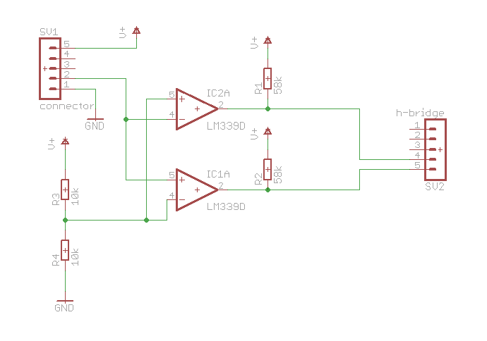
Here is a simple schematic of one of the components. The concept is that if the probed voltage is below half of the reference voltage, one LED will illuminate; otherwise, the second LED will turn on. Additionally, there is...
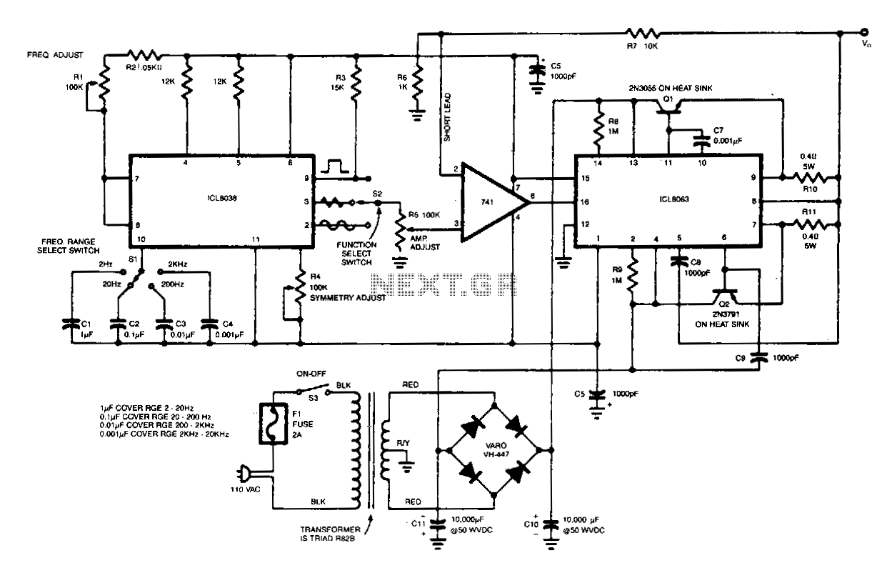
This generator will supply sine, triangular, and square waves from 2Hz to 20kHz. This complete test instrument can be plugged into a standard 110 Vac line for power. VoVT will be up to ±25 V (50 V pk-pk across...
A function generator that operates within a frequency range of 0.1 Hz to 20 MHz can be easily constructed using the MAX038 integrated circuit chip. This describes a straightforward implementation of the device. The MAX038 is a precision waveform generator...
The schematic illustrates the subwoofer amplifier stage, specifically the pre-amplifier circuit and the signal processing circuit. Notably, it features two LM3886 power ICs from the American company NS, which facilitate BTL (Bridge-Tied Load) speaker operation at an 8-ohm impedance...
Significant overengineering was necessary to replicate a previous capacitive scanner. At the local hackerspace OSAA, a brainstorming session was initiated with Pedersen, AsbjG rn, and Flemming, who quickly generated numerous creative ideas. The discussion took an interesting turn when...
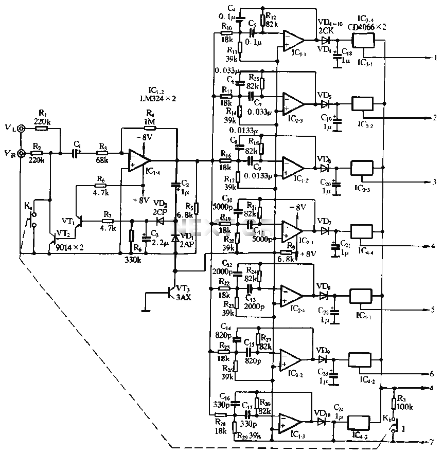
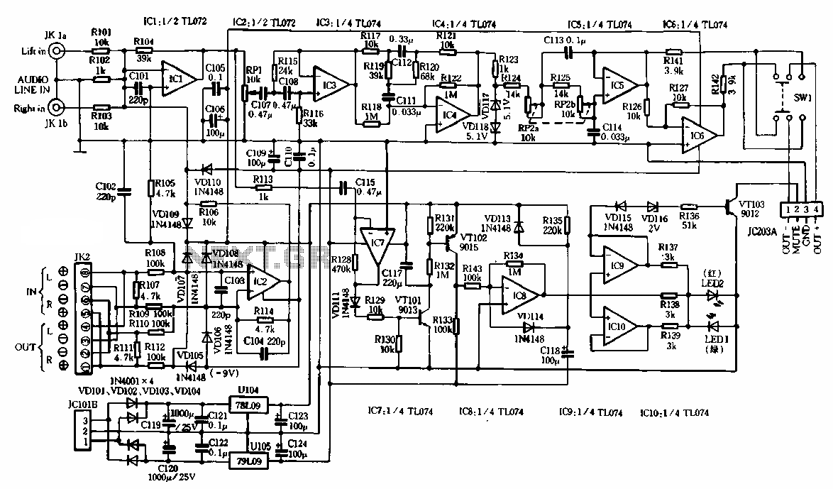
The structure and working principle of this circuit are fundamentally similar to the previous circuit, with some variations in the components used. The circuit is divided into seven bands, with center frequencies selected at 60 Hz, 150 Hz, 400...
Warning: include(partials/cookie-banner.php): Failed to open stream: Permission denied in /var/www/html/nextgr/view-circuit.php on line 713
Warning: include(): Failed opening 'partials/cookie-banner.php' for inclusion (include_path='.:/usr/share/php') in /var/www/html/nextgr/view-circuit.php on line 713