
arduino model railway control

The model railway control system integrates several components and functionalities designed to enhance user interaction and operational efficiency. The Arduino microcontroller serves as the central processing unit, receiving commands from the laptop over a USB interface. This setup allows for real-time control and flexibility in operation, making it suitable for interactive exhibits such as the one planned for the Corris Railway Museum.
PWM is utilized to modulate the voltage supplied to the train's motor, allowing for smooth acceleration and deceleration. However, the initial setup faced issues due to the power supply's inability to manage the PWM load effectively. The solution involved isolating the Arduino's power supply from the motor's power, ensuring that the control logic remained stable while the motor received adequate power from the dedicated external supply. This configuration is crucial for maintaining the integrity of the control signals and preventing system crashes.
The Darlington TIP120 transistors are employed as motor drivers in this design, providing the necessary current amplification to control the motor's operation. The common ground is vital for the transistors to function correctly, ensuring that the control signals from the Arduino can effectively switch the motor on and off.
The automation aspect of the project is facilitated through the use of a coin acceptor mechanism, which interfaces with the Arduino to track the number of coins inserted. Based on the input, the software determines the duration and speed of the train's operation. The inclusion of reed switches at strategic locations along the track allows for automated reversing and stopping at designated stations, enhancing the overall user experience.
The hardware driver circuit schematic, while noted to be rough, illustrates the connections between the Arduino, power supplies, motor drivers, and reed switches. This schematic serves as a foundational guide for replicating or modifying the system as needed. The breadboard prototype photograph provides a visual reference for the physical layout and component arrangement, showcasing the initial stages of the project development.
Overall, this model railway control system exemplifies an innovative approach to integrating electronics and software for interactive educational experiences, with potential for further enhancements and refinements in future iterations.Model railway running under computer control using the laptop to send commands over the USB port to the Arduino, which then does PWM to control the speed of the train. There were a few hiccups along the way not least of which the Arduino crashed repeatedly when the train started moving it appears that the power pack I was using didn`t like having its load being PWMed, causing voltage problems.
I resorted to running the Arduino off the USB supply, disconnecting the common 12V power input to the board, and just using that external power pack to provide power for the direction change relay and output to the loco. Make sure that you keep the ground connected though, as the Darlington TIP120s need that to be common in order to work.
The eventual use for this project is to automate the model layout in the Corris Railway Museum, and allow visitors to put coins in a slot and the train will then run for a number of returns depending on the coin put in. More coins the train runs a little quicker. The software allows for reed switches at either end of the line for reversing, as well as reed switches for stations.
The hardware driver circuit is shown here in the schematic below (I know it`s pretty rough, but it`s as good as I can do at short notice), and photo of the really dodgy looking breadboard prototype. 🔗 External reference
Related Circuits
Variable-gain amplifiers (VGAs) can be used in many types of systems, such as radio receivers. In this system, the input signal voltage depends on an. Variable-gain amplifiers (VGAs) are integral components in various electronic systems, particularly in radio receivers where...
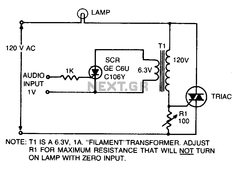
This is an on-off control with an isolated, low voltage input. The switching action occurs rapidly compared to the response time of the lamp and the human eye, resulting in an effect with audio input that resembles a proportional...
This circuit demonstrates the use of Silicon Controlled Rectifiers (SCRs) to control low-voltage pulsating DC for operating homemade LED light panels. Although the circuit utilizes an Arduino, the underlying concepts are applicable to various microcontrollers, whether through hardware interrupts...
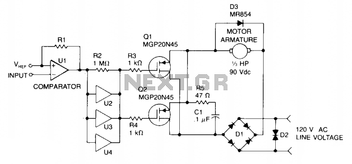
Speed control is achieved through pulse width modulation (PWM) of the gates of two MGP20N45 TMOS devices. Consequently, the motor speed is directly proportional to the pulse width of the incoming digital signal, which can be generated by a...
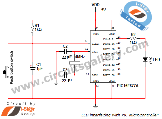
How to interface an LED with Microchip's PIC microcontroller. Connecting LEDs to a PIC microcontroller is fundamental for microcontroller development. This guide presents a simple embedded program for the PIC 16F877A to interface LEDs, making it suitable for beginners...
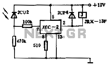
The circuit operates as a photoelectric switch utilizing a photoresistor. It exhibits high sensitivity, particularly in controlling a light relay. Under low illumination, the transistor (VT) remains non-conductive. When the illumination reaches a certain threshold, the resistance of the...