
Gate automatic lamp circuit

The automatic lighting circuit described operates based on the interaction between various components, primarily utilizing integrated circuits for efficient operation. The CD4093 NAND gate IC serves as the core logic device, interfacing with sensors that detect the state of doors and windows. When the magnetic field from a magnet is present, the circuit remains in a closed state, allowing current to flow through the system. This condition is maintained until the door is opened, at which point the magnetic reed relay disconnects, triggering a change in the circuit's output.
The light detection mechanism is achieved through a combination of a phototransistor and a resistor. During nighttime conditions, when ambient light levels are low, the phototransistor becomes non-conductive, leading to a low output signal. Conversely, during daylight, the phototransistor conducts, resulting in a high output signal. This differentiation between day and night is crucial for the operation of the lighting system, ensuring that lights are only activated when necessary.
The RS flip-flop configuration within the circuit serves to manage the state of the output based on the input signals received from the sensors. The truth table of the RS flip-flop indicates that the output will only transition to an active state when the door is opened (input S = 1) during nighttime conditions (input R = 0). Consequently, when the output is activated, it energizes a solid-state relay (SSR), which in turn powers the lighting element. The incorporation of a light-emitting diode (LED) provides a visual indication of the system's operational status.
A delay circuit is also integrated into the design, allowing for a predetermined duration of illumination after the door is opened. This feature is particularly beneficial in scenarios where immediate closure of the door may not occur, as it provides sufficient time for individuals to enter or exit the space. The delay is achieved through a CMOS circuit that utilizes a capacitor to extend the time before the light is turned off.
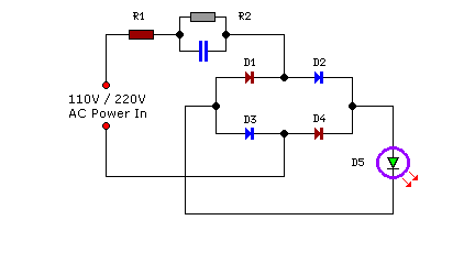
The power supply section of the circuit is designed to be efficient, utilizing a rectifier and voltage regulator to ensure stable operation without generating excessive heat. This design consideration enhances the longevity and reliability of the circuit. Components such as tantalum electrolytic capacitors are recommended for their low leakage current, which contributes to the overall efficiency of the system.
Overall, this automatic lighting circuit exemplifies a practical application of digital logic and sensor integration, providing a reliable solution for automated lighting control based on environmental conditions and user interaction.- The use of a number of integrated circuits rather gated automatic lighting circuit device formed, which consists of door and window components of the sensor, CD4093 digital integrated circuits with state relay and power supply circuit. Usually closed when the room f J. K by the magnetic field of the magnet, the electrical connection is closed, the inverter f Chuan I input high level, after inverting input rP, is low; when the deduction liter door, away from the T magnet reed relays, K jump contacts Ji door input is low, the output is high, namely: the door shut - o; door Ji-1, phototransistor WlP and R, composed of light twist circuit at night without light, VTP off, the output for the "O"; when Bai Tianbai light, Vir conduction, the output is "1." RS © NAND gate I and composed of typical fire triggers, J '] control signal and the control signals, respectively , as S (set to "l") end and R (set to "()") side of the input signal. From the RS flip-flop truth table (see Table 7 1) shows that only when R = O (ie the night, no light), S a 1 (door is opened), whose output Q that is only for the first feet " ..
" After t inverter inverting the first feet high output power + to make a diode VT conduction, solid state relays SSR opened, F lamp is lit, the light emitting diode while I, ED also lit indicates. And when R = L (ie n days, there is light). Or when so (door closed) is called, all so that the output Ql, through gates t anti After phase so V1I off, SSR off Ge, F spider will not be illuminated.
VD1, (, I and R; cyanosis to extend Trent lU Road, elbow 'i "signal delay of about 10 s so that the door is opened. When people enter (a) Li Yi Ge I, when the door not be closed, electricity spider E , but to delay 40s then off.
the delay circuit full advantage of the CMOS circuit high input Frl + / Lt larger than 10Mn), heard this training using smaller capacitors will machi obtain a relatively longer delay time: 1 as the book machine DC voltage mountain f buck, VD2 ~ VDa rectifier, vs regulator after obtaining the entire power supply section without heating element [U electrode consumption province, can pass lU among pregnant published work, the same year the electricity suddenly energized blood will not exceed ikWh "] circuit I -IV using Schmitt NAND gate 4 blocks of digital integrated circuits CI) 4003.SSR use IC, type solid state relays TA (, OIS, the maximum drive capability IA.C, suddenly find using C, 1 {B400V polypropylene capacitors , a claim .. electrolytic capacitor leakage current as small as possible for the best use tantalum electrolytic door sensor suppliers to seek common ground dagger cases, no special requirements other components.
Related Circuits
This operational amplifier (opamp) is available at a low cost. The AD8099 is a very fast opamp with a slew rate of 1600 V/µs and features high-impedance inputs with low input capacitance. Its bandwidth is sufficiently large that at...
This is a range of IF signal circuits that may be of interest to radio hobbyists and professionals alike. Transistors T1 and T2 form an astable multivibrator oscillating in the audio frequency range of 1 to 2 kHz. An...

In this tutorial, the functioning of the memory card circuit in mobile phones will be explored. The previous post discussed the pin-outs and types of memory cards utilized in cellular devices. The accompanying block diagram illustrates how the removable...
Compact yet highly functional, this is a straightforward and efficient LED circuit designed to operate directly from the AC mains supply, ranging from 100 volts to 230 volts. This LED circuit utilizes a few essential components to achieve efficient...

This is an intercom circuit that utilizes the LM380 as the audio amplifier and two transistors for the microphone preamplifier. The sound quality is sufficiently good while maintaining a low construction cost. The circuit comprises two identical intercom units,...
The RF oscillator utilizes inverter N2 and a 10.7 MHz ceramic filter to drive the parallel combination of inverters N4 to N6 through inverter N3. Since these inverters are connected in parallel, the output impedance is low, allowing direct...