
SimpleCircuit IF Signal Generator

The described circuit features a dual-stage configuration utilizing transistors T1 and T2 to create an astable multivibrator. This multivibrator generates a square wave signal with a frequency adjustable between 1 kHz and 2 kHz, making it suitable for audio applications. The output from the multivibrator is fed into the RF oscillator circuit, which is centered around transistor T3. This transistor operates as a high-frequency oscillator, producing a carrier frequency of 455 kHz, a standard frequency used in many radio applications.
Capacitor C3 serves as a coupling capacitor, allowing the audio frequency signal to pass while blocking any DC components. The tank circuit at the collector of transistor T3 is critical for tuning the oscillator. The inclusion of a medium wave oscillator coil from a transistor radio, combined with a fixed 100 pF capacitor C5 and part of a unit capacitor (C6), creates a resonant circuit that defines the oscillator's frequency.
For applications requiring different frequencies, the circuit can be modified by substituting the existing filter or resonator with one that matches the desired frequency. Adjustments to the tank circuit can fine-tune the oscillator's performance, ensuring optimal operation. The resistors R6 and R7 provide an additional means of control, allowing for slight modifications to the circuit's characteristics to accommodate specific requirements or conditions. This flexibility makes the circuit highly adaptable for various radio frequency applications, appealing to both hobbyists and professionals in the field.Here is a able ambit of IF arresting architect which may be of absorption to radio hobbyists and professionals alike. Transistors T1 and T2 anatomy an astable multivibrator aquiver in the audio abundance ambit of 1 to 2 kHz.
RF oscillator is congenital about transistor T3. Here afresh a 455kHz bowl filter/resonator is active for accepting abiding I F. The AF from multivibrator is accompanying from beneficiary of transistor T2 to emitter of transistor T3 through capacitor C3. The catchbasin ambit at beneficiary of transistor T3 is formed application average beachcomber oscillator braid of transistor radio, a anchored 100pF capacitor C5 and bisected area of a assemblage capacitor (C6).
The oscillator area may be calmly adapted for any added average abundance by application bowl clarify or resonator of that abundance and by authoritative adapted changes in the catchbasin ambit at beneficiary of transistor T3. Slight acclimation of bent can be afflicted by capricious ethics of resistors R6 and R7, if required 🔗 External reference
Related Circuits
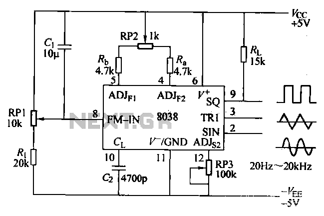
The ICL8038 function generator is an audio composition device that utilizes the ICL8038 integrated circuit. The resistance Ri potentiometer RP1 is used to determine the flow potential. Typically, the output is set to approximately 2Vcc / 3. Lowering the...
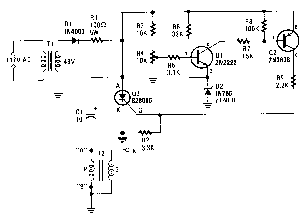
A step-down transformer T1 reduces the incoming line voltage to approximately 48 Vac, which is then rectified by diode D1. The resulting direct current charges capacitor C1 through a current-limiting resistor R1 to a voltage level set by R4....
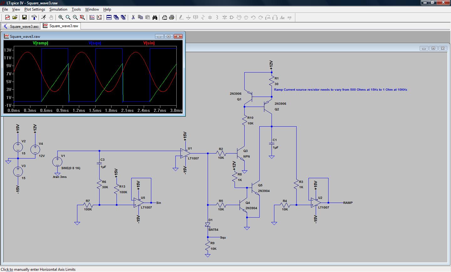
A simple low-end audio function generator is being designed to utilize a sine wave output for testing ADC resolution and as a baseband signal for RF projects, with an emphasis on achieving very low total harmonic distortion (THD). The...
LVDT (linear voltage differential transformer) is widely used as a linear position sensor. The AD589 integrated circuit provides a complete solution for LVDT. The Linear Voltage Differential Transformer (LVDT) is a highly precise sensor commonly employed for measuring linear displacement....
The following circuit presents a Bell Ring Generator Electronic Circuit Diagram. Features include the generation of a dual-tone bell ringing, similar to most standard bell systems. The Bell Ring Generator circuit is designed to produce a dual-tone output that mimics...
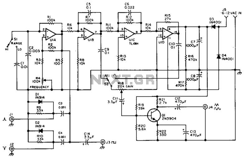
A quad op-amp serves as the core component of this function generator. U1A produces a square wave, which is outputted to J8. J1 and J2 are pulse outputs derived from differentiating the square wave. The integrator U1B creates a...