
Gel electrophoresis power supply

The mini-gel electrophoresis apparatus is designed for the separation of nucleic acids such as DNA and RNA. The core components of this setup typically include a gel casting tray, a comb for creating wells, a power supply, and an electrophoresis chamber. The gel is usually made from agarose, which provides a matrix through which the nucleic acids can migrate when an electric field is applied.
To assemble the mini-gel electrophoresis system, the agarose gel is prepared by mixing agarose powder with a buffer solution and heating it until it dissolves. Once cooled, the gel is poured into the casting tray, and the comb is inserted to create wells for sample loading. After the gel solidifies, the comb is removed, and the gel is placed in the electrophoresis chamber filled with a running buffer.
The samples of DNA or RNA are loaded into the wells, and the chamber is connected to a power supply. When the power is turned on, the negatively charged nucleic acids migrate towards the positive electrode due to the applied electric field. The migration speed is influenced by the size of the nucleic acids, allowing for separation based on size.
Post-electrophoresis, the gel can be stained with a DNA-binding dye, such as ethidium bromide or SYBR Green, to visualize the separated nucleic acids under UV light. This process is essential for various applications in molecular biology, including cloning, sequencing, and genetic analysis. The mini-gel electrophoresis system is favored for its simplicity, efficiency, and effectiveness in analyzing nucleic acids in laboratory settings.In previous Instructables tutorials we have described how to make equipment used for DNA electrophoresis and imaging. These include a mini-gel electro.. 🔗 External reference
Related Circuits
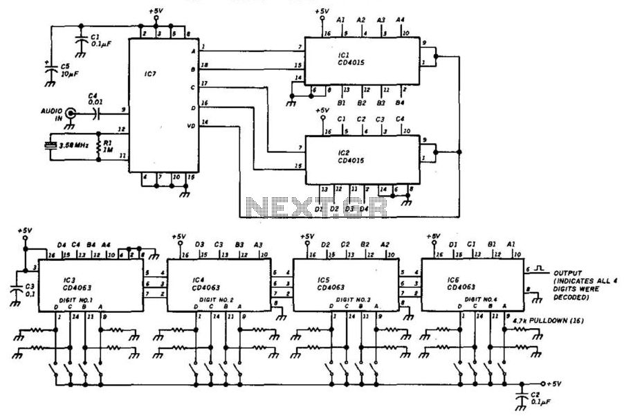
This decoder will respond to a preselected 4-digit DTMF number. IC7 is a Radio Shack IC device (part #276-1303). The logic is all CMOS. The digits are selected by SW1 and SW2, a pair of 8-position DIP switches. The described...
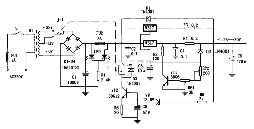
The adaptive adjustable power supply is illustrated in the accompanying figure. The power supply utilizes an LM317 regulator device, and an adaptive switching circuit that automatically adjusts the input voltage based on the output voltage level. This mechanism reduces...
The two circuits demonstrate the process of opening a relay contact shortly after the ignition or light switch is turned off. The capacitor is charged, and the relay remains closed until the voltage at the diode anode reaches +12...
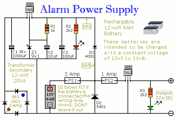
This power supply is designed for the Modular Burglar Alarm but is suitable for various applications. It delivers a 12-volt output with a maximum current of 1 amp. In case of a mains failure, the backup battery activates immediately,...
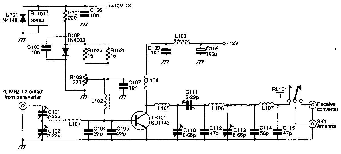
This 70 MHz RF power amplifier circuit utilizes the SD1143 transistor, which offers a gain of approximately 14 dB in this configuration. The design leverages the characteristics of a 175 MHz device. The RF power amplifier circuit designed around the...
The circuit is designed to create a power amplifier that utilizes E80CC and EL34 vacuum tubes to achieve optimal performance, providing an output of 35 Watts. The power amplifier circuit employs E80CC and EL34 vacuum tubes, which are known for...