
Power-Off Time Delay Relay circuit

The described circuits utilize a relay and a capacitor to control the timing of the relay operation following the deactivation of the ignition or light switch. When the switch is turned off, the capacitor begins to discharge through the relay coil, maintaining the relay in a closed position for a brief period. This delay allows for a controlled opening of the relay contacts, which can be advantageous in various automotive or lighting applications where a gradual disconnection is preferred to prevent electrical surges or abrupt changes in circuit conditions.
In the circuit configuration, a diode is placed in parallel with the relay coil to protect the circuit from back EMF generated when the relay is switched off. The anode of the diode connects to the positive voltage supply, while the cathode connects to the relay coil. The capacitor is charged to the supply voltage when the ignition or light switch is in the 'on' position. Once the switch is turned off, the capacitor begins to discharge through the relay coil, allowing the relay to remain activated until the capacitor voltage drops below the necessary threshold, which is indicated by the +12 volts at the diode anode.
The timing of the relay opening can be adjusted by changing the capacitance value or the resistance in the discharge path, allowing for flexible control based on specific application requirements. This design is particularly useful in automotive lighting systems where a delay in turning off the lights after the ignition is switched off can enhance safety and visibility.The two circuits illustrate opening a relay contact a short time after the ignition or ligh switch is turned off. The capacitor is charged and the relay is closed when the voltage at the diode anode rises to +12 volts..
🔗 External reference
Related Circuits
This is an electric thermometer circuit composed of the LM134. In the circuit, the voltage or current output by the LM134 is proportional to the thermodynamic temperature, which can be read on a 100 µA meter. The test temperature...
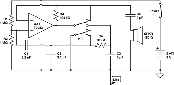
The circuit operates in receive mode, with the Push-To-Talk (PTT) switch enabling transmit mode. The speaker functions as both a microphone and a speaker. Most systems observed utilize a rocking armature transducer for the speaker. There is no base...
Although many album titles that were once available on vinyl are gradually being released on CDs, not all titles are accessible. It is possible that there are valuable records in a collection that one might wish to convert to...
The following circuit illustrates the sensor circuit diagram for automatic room lights. This circuit is based on the CD4017 integrated circuit (IC) and features the use of two light-dependent resistors (LDRs). The automatic room light circuit utilizes the CD4017 decade...
A frequency synthesizer circuit diagram has been found, but clarification is needed regarding a component connected to VDD from pin 9, VSS from pin 8, and pin 12, which is linked to the phase comparator 2. The component in...
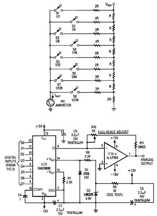
Figure A illustrates an R/2R resistor ladder. Each closed switch increases the current output. A basic channel A/D converter is depicted in Figure B. The voltage reference (D2) is shared among all channels, while the value of the dropping...