
GENERAL DIAGRAM OF MOTOR CONTROLLER

No description available.
Related Circuits
To build a stepper motor tester, the circuit includes two sets of drivers that support both unipolar and bipolar stepper motors. The control circuit and driver circuit are powered by separate supplies, allowing compatibility with a wider range of...
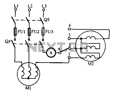
Drying the motor winding circuit current imbalance. Below is a circuit diagram of the motor winding current imbalance drying. The circuit for drying motor winding current imbalance is designed to address the issue of uneven current distribution across the windings...
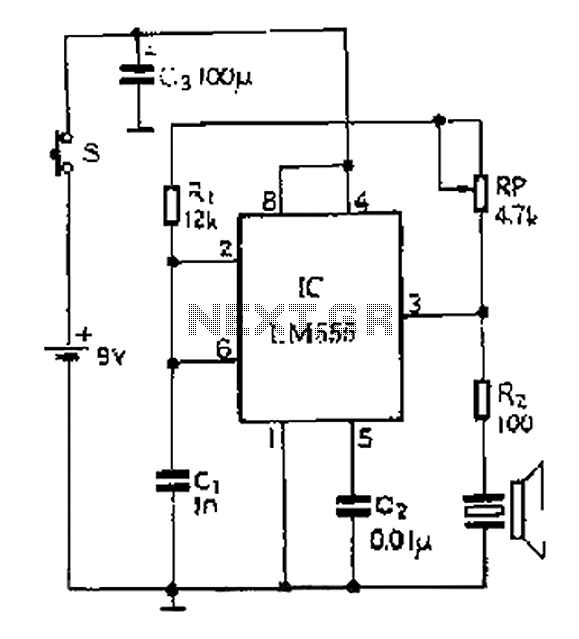
A 40 kHz ultrasonic transmitter circuit utilizes the LM555 timer as a time base circuit along with external components to create a 40 kHz multivibrator. The resistance of the adjustable resistor RP can modify the oscillation frequency. The output...
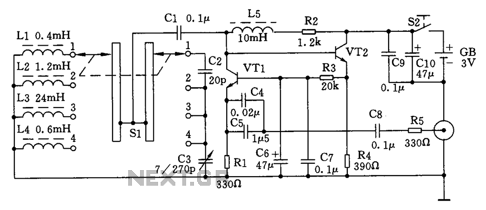
This is a simple high-frequency signal generator. By changing the inductance of the LC resonant circuit using the band switch S1, the high-frequency oscillation frequency range can be altered. The generator is divided into four frequency stages: the first...
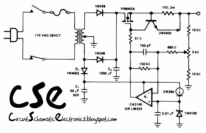
This circuit utilizes the operational amplifier IC LM324 to drive the VN64GA with an error signal and to regulate the output voltage. The output voltage generated is pulsating DC, which is suitable for battery charging applications. Additionally, this circuit...
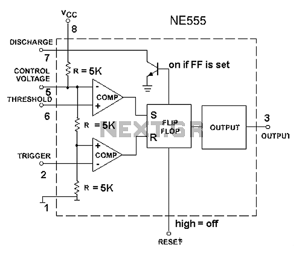
The 555 timer circuit, regardless of the manufacturer, has a consistent internal structure and performance. Various manufacturers produce different models of the 555 timer, including MC555, CA555, XR555, LM555, as well as domestic models like SL555, FX555, and 5G1555....