
Motor winding circuit diagram of the current imbalance dried

The circuit for drying motor winding current imbalance is designed to address the issue of uneven current distribution across the windings of an electric motor. This imbalance can lead to overheating, reduced efficiency, and potential damage to the motor. The schematic typically includes components such as resistors, capacitors, diodes, and a microcontroller or relay for monitoring and control.
In the circuit, current sensors are strategically placed to measure the current flowing through each winding. These sensors provide real-time feedback to the control unit, which processes the data to determine if any windings are receiving an unequal amount of current. If an imbalance is detected, the control unit activates a drying sequence.
The drying process usually involves applying a controlled voltage to the affected winding(s) to facilitate the evaporation of moisture that may have accumulated due to environmental factors. This is often achieved through the use of resistive heating elements that can be integrated into the circuit. The resistors are chosen based on their power rating to ensure they can handle the necessary load without overheating.
Diodes may be included to protect the circuit from reverse voltage spikes, which can occur when the motor is switched off or during transient conditions. Additionally, capacitors can be used to smooth out voltage fluctuations and improve the overall stability of the circuit.
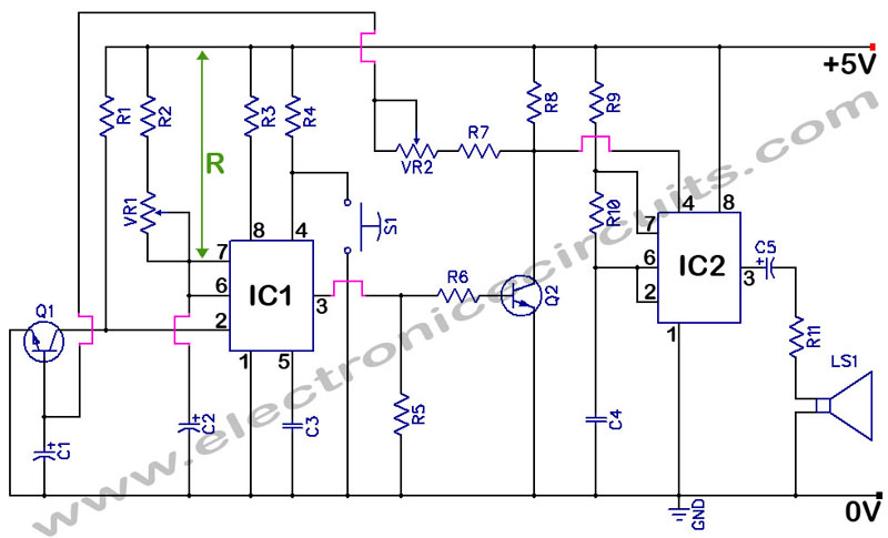
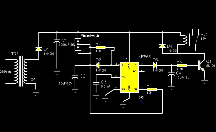
The final output of the circuit is a balanced current distribution across the motor windings, ensuring optimal performance and longevity of the motor. Proper design and implementation of this circuit are crucial for maintaining the reliability of electric motors in various applications.Drying the motor winding circuit current imbalance Below is a circuit diagram of the motor winding current imbalance drying:
Related Circuits
555 Timer with Audio Alarm Circuit. This circuit serves as a straightforward electronic timer equipped with an audio alarm feature. The 555 timer is a versatile integrated circuit widely used in various timer, delay, pulse generation, and oscillator applications. In...
A Variable DC Power Supply is an essential tool for electronics hobbyists. This circuit is not entirely new, but it is simple, reliable, robust, and short-proof, offering variable voltage up to 24V and variable current limiting up to 2A....
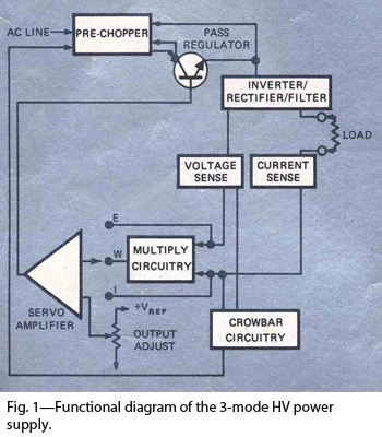
By combining switching and series-pass techniques, the designer of this high-voltage supply achieved 0.01% regulation at power levels up to 100W. The high-voltage power supply employs a hybrid approach that integrates both switching and series-pass regulation methods to achieve exceptional...
This magic lamp appears to be an ordinary frosted light bulb with a rather unusual characteristic. Whenever a finger touches the base threads and center contact, the lamp magically lights up without wires. It creates a compelling illusion if...

The construction and operation of brushless motor windings are based on the principle of triangular coils. Through the switch, the stator coil current can be cycled, resulting in the formation of a rotating magnetic field. The cycle of the...
The circuit diagram illustrates a rotation sensor that activates a device, such as a motor or buzzer, when the circuit assembly is rotated. The design is based on the fundamental operation of a 555 timer. The rotation sensor circuit utilizes...