
General Infrared Remote Controlled Relay

The relay circuit described functions by receiving signals from an infrared (IR) remote control, which typically operates at a frequency of around 38 kHz. The circuit is designed to decode these IR signals and activate a relay, allowing for the control of various electronic devices.
The core components of the circuit include an infrared receiver module, a microcontroller or a dedicated decoder IC, and a relay. The infrared receiver module detects the IR signals emitted by the remote control. Upon receiving a signal, the module outputs a digital signal to the microcontroller or decoder IC.
The microcontroller processes the received signal and determines the corresponding action based on the specific button pressed on the remote control. This processing may involve simple logic or more complex programming, depending on the desired functionality. The output from the microcontroller is then used to energize the relay coil, which closes or opens the relay contacts, thereby controlling the connected load.
Power supply considerations are crucial for the proper operation of the circuit. The circuit typically requires a regulated power source that can supply the necessary voltage and current for both the infrared receiver and the relay. Commonly used relays can handle various loads, allowing the circuit to control appliances such as lights, fans, or other electronic devices.
In summary, this relay circuit provides a versatile solution for remote control applications, leveraging the widespread use of infrared remote controls to enable wireless operation of electrical devices.This relay circuit is controlled by almost any type of infrared remote controller. This circuit works on assumption that almost all remote controller use high.. 🔗 External reference
Related Circuits
An IR remote control is a widely used device found with televisions, VCRs, and home theaters. It can also be utilized to control personal devices such as lights and air conditioning. Remote controls operate using infrared (IR) light, which...
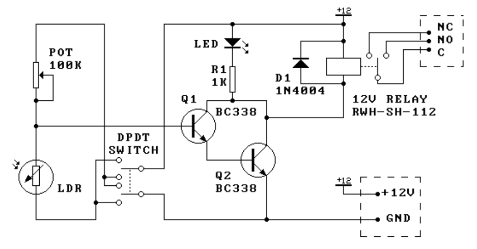
This kit is the most basic, practical circuit to build using an LDR to turn on a relay. The two transistors connected as a Darlington pair give the circuit enough sensitivity, while the trimpot gives sensitivity adjustment. The switching...
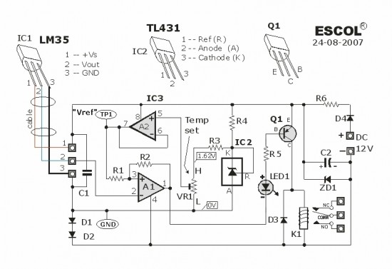
This temperature-controlled relay circuit is a simple yet highly accurate thermal control circuit that can be used in applications requiring automatic temperature regulation. The temperature-controlled relay circuit operates by monitoring the ambient temperature and activating or deactivating a connected load...
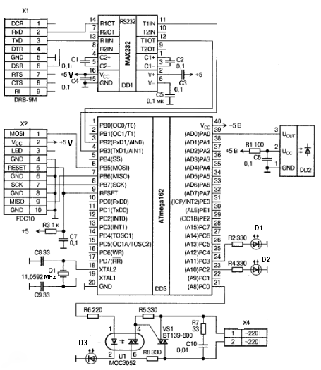
Remote-controlled light switches are increasingly popular. DIY stores offer affordable sets that include multiple light switches and a remote control unit, allowing users to manage lighting from their armchairs. However, controlling the lighting while away from home can be...
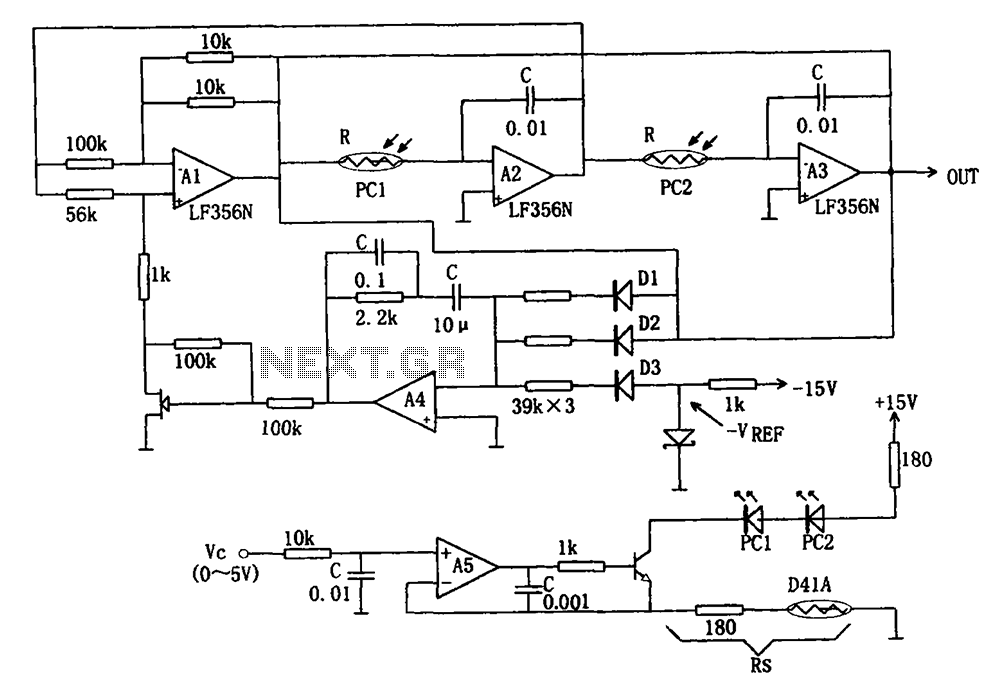
The wideband sinusoidal voltage-controlled oscillator circuit is designed such that the oscillation frequency is determined by an integrating resistor R and a capacitor C. The voltage-controlled oscillator is constituted by the applied control voltage Vc and a control resistor...
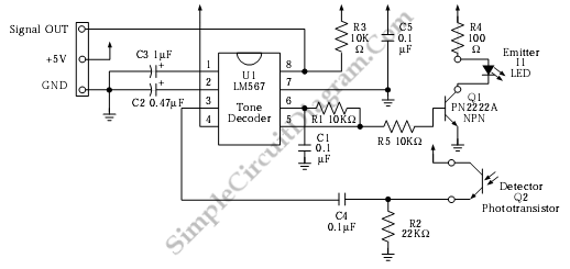
This is an infrared (IR) proximity detector circuit. A matched infrared emitter and detector pair is utilized in this circuit. The voltage-controlled oscillator (VCO) section of the LM567 tone detector integrated circuit (IC) is employed to set the emitter...