
Light/dark relay switch

More: Look what happens when the relay turns on: the input voltage drops slightly (say around 20 mV) when the relay turns on and loads the circuit. If the voltage applied to the base-emitter junction of Q1 is only just sufficient to turn it on then this slight drop will immediately start to turn Q1 off. But then with the relay load reducing the supply voltage will start to rise & Q1 will start to turn on etc. This leads to the relay chattering as it rapidly turns on/off. (This problem is overcome in K79B by the built-in hysteresis of the op-amp, and the Schmidt Trigger arrangement of the circuit in K79C.)
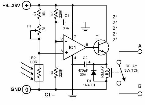
This circuit utilizes a Light Dependent Resistor (LDR) as a light sensor, which changes its resistance based on the ambient light level. When the light intensity reaches a predetermined threshold, the LDR's resistance decreases, allowing current to flow through the circuit. The Darlington pair configuration, consisting of two transistors (Q1 and Q2), amplifies the current from the LDR, providing sufficient gain to drive the relay.
A trimpot is included in the design to allow for fine-tuning of the sensitivity of the circuit. By adjusting the resistance of the trimpot, the user can set the light level at which the relay will activate. This feature is particularly useful for applications that require specific light conditions for operation.
The relay serves as an output device that can control larger loads, such as lights or alarms, based on the detected light levels. However, a notable issue arises with the relay's operation when the light levels change slowly. The circuit may experience chattering, where the relay rapidly toggles between the on and off states due to slight fluctuations in the input voltage caused by the relay’s own load. This occurs because the small voltage drop across the relay when it activates can momentarily reduce the base-emitter voltage of Q1, causing it to turn off, which then allows the voltage to recover and turn Q1 back on again, creating an unstable condition.
To mitigate this chattering effect, alternative circuit designs, such as those found in K79B and K79C, implement hysteresis and Schmidt Trigger configurations. These designs introduce a degree of feedback that stabilizes the switching behavior of the circuit, ensuring that the relay operates reliably without unintended toggling during slow light transitions.This kit is the most basic, practical circuit to build using an LDR to turn on a relay. The two transistors connected as a Darlington pair give the circuit enough sensitivity, while the trimpot give sensitivity adjustment. The switching point of the relay is dependent on the supply voltage and temperature. This circuit is satisfactory if the changes in light level to be detected are large and the transition is quick - for example, a person walking past a doorway.
But an inherent problem of the circuit is chattering of the relay for slowly changing light levels just at the transistion point between turning on/odd and vice versa. Look what happens when the relay turns on: the input voltage drops slightly (say around 20 mV) when the relay turns on and loads the circuit. If the voltage applied to the base-emitter junction of Q1 is only just sufficient to turn it on then this slight drop will immediately start to turn Q1 off.
But then with the relay load reducing the supply voltage will start to rise & Q1 will start to turn on etc. This leads to the relay chattering as it rapidly turns on/off. (This problem is overcome in K79B by the built-in hysteresis of the op-amp, and the Schmidt Trigger arrangment of the circuit in K79C.)
🔗 External reference
Related Circuits
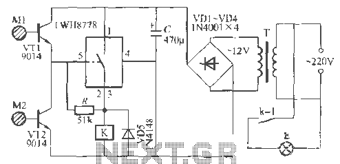
The Rw A77S power system utilizes an integrated circuit fabrication design featuring a dual touch light switch. It employs a transformer (T) for power conversion, a rectifier (VD4), and a capacitor (C) for filtering, resulting in a 12V DC...
A video switcher circuit is required to display multiple sources on a single monitor. The circuit schematic below features the MAX454, which serves as the core component of this video switcher. The MAX454 is a video multiplexer-amplifier manufactured by...
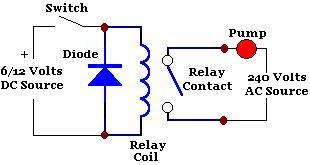
A relay is an isolated switch, with no direct connection between the switching device and the load. Relays are commonly used to control high-voltage devices, protecting sensitive low-voltage components from damage. Various types of relays exist, but electromechanical relays...
The brightness of the surrounding light controls the function of this circuit. The light sensor used in this circuit is a light-dependent resistor (LDR). This LDR is connected to the non-inverting input of the 741 op-amp IC. Once the...
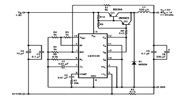
The schematic diagram below illustrates a 5V/1A Step-Down Switching Regulator utilizing the LM2524D Regulating Pulse Width Modulator (PWM). Additional parameters, PC board layout, stuffing diagram, and more information can be found in the LM2524D datasheet. The circuit design features the...
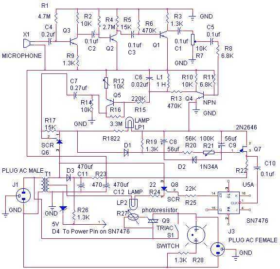
The whistle switch allows you to turn on, or off, an appliance by whistling at it. I originally built the whistle switch in 1974. Do not attempt to duplicate it from the schematic below, but instead, understand the functions...