
General-Purpose Jfet Preamp Circuit

The described JFET (Junction Field Effect Transistor) preamplifier is designed to amplify low-level audio signals while maintaining high fidelity across a broad frequency range. With a gain of around 20 dB, this preamplifier effectively boosts weak signals, making it suitable for applications involving high-impedance sources, such as microphones or guitar pickups.
The bandwidth specification of over 100 kHz indicates that the preamplifier can handle a wide range of audio frequencies, ensuring that both low and high-frequency signals are accurately amplified without distortion. This characteristic is essential in audio applications where clarity and detail are paramount.
The circuit typically consists of a single JFET transistor, which operates in the common-source configuration to achieve the desired gain. Biasing resistors are employed to set the operating point of the JFET, ensuring optimal performance. Coupling capacitors may be included at the input and output stages to block any DC offset while allowing AC audio signals to pass through.
Additionally, feedback resistors may be integrated to stabilize the gain and improve linearity, thus enhancing the overall performance of the amplifier. The power supply should be adequately decoupled to minimize noise and ensure stable operation across varying load conditions.
This JFET preamplifier design is particularly advantageous in professional audio equipment, where high input impedance is critical for interfacing with various audio sources while preserving signal integrity. This JFET preamplifier has a gain of about 20 dB and a bandwidth of over 100 kHz. It is useful as a low-level audio amplifier for high- impedance sources.
Related Circuits
The LM1036 is a DC-controlled circuit designed for managing tone (bass/treble), volume, and balance in stereo applications, such as car radios, televisions, and audio systems. It features an additional control input for easy loudness compensation. Four control inputs allow...
The circuit indicates two different water temperature trip points by activating LEDs when the specified temperatures are reached. It is built around the LM2904 dual operational amplifier, which is powered by a 12 V automotive system. A thermistor is...
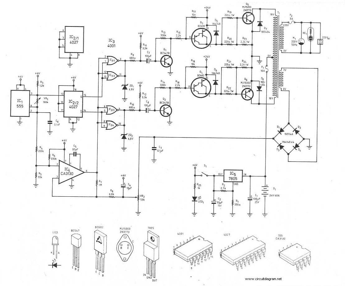
This is the schematic diagram of a 300W power inverter circuit. The inverter utilizes the MJ15003 power transistor for final amplification. If the MJ15003 transistor is difficult to source, it can be replaced with a 2N3773. The inverter is...
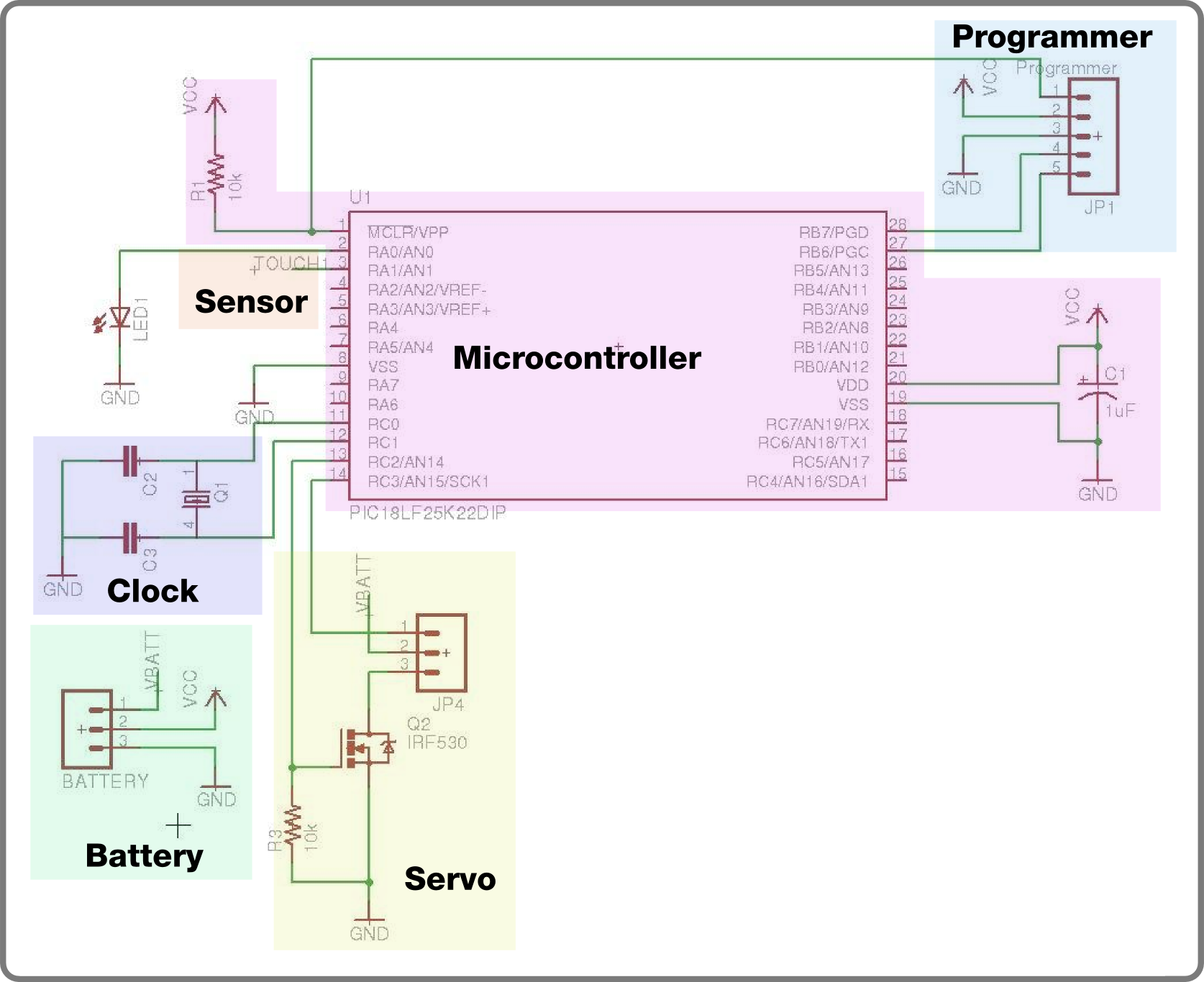
For the second build in the Make It Last Build Series, a robotic plant is being constructed. This week focuses on assembling the control circuit, which will be used in future weeks to animate the plant. The basic circuit...
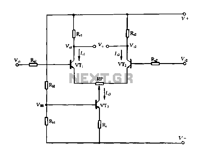
A differential amplifier with a constant current source is illustrated in Figure 1-27. As long as capacitor C3 is maintained at a constant value, capacitors C1 and C2 cannot be simultaneously increased or decreased, preventing voltage drift. The differential...
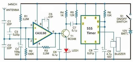
Cellular phone detector circuit schematic using common electronic parts The cellular phone detector circuit is designed to identify the presence of a cellular phone within a specified range. This circuit utilizes basic electronic components, making it accessible for hobbyists and...