
Generating a simple sine wave

The circuit for generating the sine wave carrier consists of a square wave oscillator followed by an LC low-pass filter configured as a pi filter. The oscillator can be implemented using a simple 555 timer circuit or a dedicated square wave oscillator IC. The output of the oscillator feeds into the LC filter, which is designed to have a cutoff frequency around 5 MHz to effectively attenuate higher harmonics while preserving the fundamental frequency at 3.6864 MHz.
The LC filter utilizes an inductor (L) and two capacitors (C1 and C2) arranged in a pi configuration. The values of these components can be calculated using the standard formula for the cutoff frequency of an LC low-pass filter:
\[ f_c = \frac{1}{2\pi \sqrt{LC}} \]
Where \( f_c \) is the cutoff frequency, \( L \) is the inductance in henries, and \( C \) is the capacitance in farads. Selecting appropriate values for L and C will ensure that the filter effectively suppresses unwanted harmonics while allowing the desired frequency to pass through.
In practical applications, the choice of components may vary based on availability and desired performance characteristics. The use of SMD components can enhance the compactness of the circuit and allow for more precise tuning. Additionally, a PCB layout can improve the overall performance by minimizing parasitic inductance and capacitance, which can affect the filter's response.
For testing and validation, an oscilloscope can be employed to observe the output waveform after the filter. The FFT analysis will confirm the harmonic content and ensure that the signal meets the requirements for the intended application. This process illustrates the effectiveness of using a square wave oscillator combined with a low-pass filter to generate a sine wave suitable for magnetic transponder systems and low-frequency digital communications.I needed a sine wave carrier for a magnetic transponder system I am working on. Various types of crystal based oscillator are available such as the Pierce, but these can be tricky to design and ensure they work correctly. Rich suggested using a square wave oscillator with a filter to turn it into a sine wave. The filter attenuates all frequencies except the fundamental frequency, which should remove much of the square wave. Over a couple of nights I tested this in ltspice then built it on a breadboard and checked the real life results. The filter used is a simple LC low pass, called a pi filter due to the shape. ltspice can easily be used to test a filter and produce an FFT to visualise the response. The circuit used for testing is shown below and uses nothing more than a pulsed voltage source (to generate a square wave) and the filter.
The value of 3. 6864Mhz was chosen as it is a commonly available oscillator that divides very nicely into serial baud rates, making it excellent for serial communication. Simulating a few cycles of this provides the waveforms shown below, which verify the square wave and the resulting "sine", which looks a little triangular at a first glance.
The FFT shows that the first harmonic is around -30dB, others are far below -40dB. The sine wave is not perfect in the simulation but looks quite reasonable, so it is time to build a real circuit to test. Whilst the simulator is perfect, real life is not. The circuit was built on a breadboard with an AEL crystal, Murata inductor and ordinary ceramic capacitors.
Using my Rigol DS1052E I captured data from the "post filter" node at 250Msa/sec for 1Meg worth of samples, using the "long memory" option. The graphic below shows the slightly rough sine wave, the frequency counter at the top right clearly shows an almost exact 3.
6864Mhz reading. This was fed into Sigview (a time limited demo is available that works well). A basic FFT was produced from the CSV data which clearly shows a strong peak at 3. 6864Mhz and all harmonics below -60dB. These results are excellent and exceeded what I expected from my initial tests. Which gives a cut-off of approximately 5Mhz using standard value components. SMD parts are often available in a wider selection of values for the same price so a more specific filter could be designed on a PCB. However this is still well below the 2nd harmonic frequency (7. 3728Mhz) so is a perfectly acceptable filter. Although this sine wave is nowhere near as clean as a proper crystal or DDS generated signal it is cheap, simple to construct and should work as a carrier for low frequency digital transmission to an acceptable degree.
The total cost is around £3 in single quantities and would be much cheaper at volume. 🔗 External reference
Related Circuits
This circuit utilizes the widely available LM3914 integrated circuit (IC). The LM3914 is straightforward to operate, does not require external voltage regulators due to its built-in voltage regulation, and can be powered from nearly any voltage source. This makes...
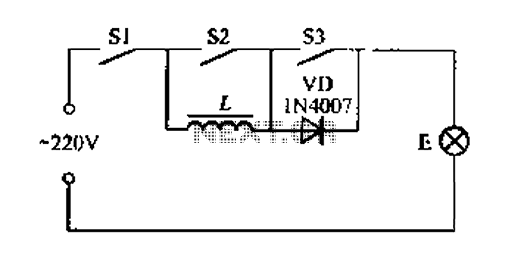
A portable four dimmer switch circuit is illustrated in Figure 8, featuring a four-speed brightness adjustment. When switches S1, S2, and S3 are all closed, the lamp operates at its brightest setting. When S1 and S2 are closed while...
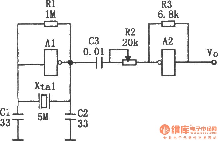
The sine wave generator composed of an inverter is illustrated in the chart. This circuit can produce a high-stability sine wave at frequencies exceeding a few megahertz. In the diagram, A1 and the crystal oscillator create an oscillating circuit,...
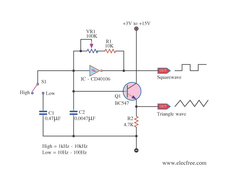
This is a circuit function generator that produces triangle and square wave signals. It utilizes an IC 40106 and a BC547 transistor. The variable resistor VR1 is used to control the frequency output, while switch S3 serves as a...

In conventional triangular-wave oscillators, hysteresis from positive feedback in the Schmitt trigger determines the voltage levels and amplitude of the triangular waves. With this topology, it is difficult to independently vary the voltage levels and amplitude of the output...
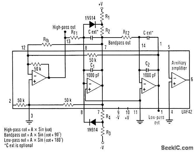
A three-phase sine-wave oscillator can be constructed using a single UAF42 state variable filter, along with a few resistors and diodes. The circuit provides three output nodes: high-pass output, bandpass output, and low-pass output. The signals at the bandpass...