
ONE FILTER THREE PHASE SINE WAVE GENERATOR

The UAF42 state variable filter serves as the core component of the three-phase sine-wave oscillator. This integrated circuit is designed to provide versatile filtering capabilities, allowing for the generation of sine waves at various phases. The high-pass, bandpass, and low-pass outputs facilitate the extraction of different frequency components from the generated signal, making it suitable for a variety of applications such as motor drives, signal processing, and waveform generation.
In this circuit, the high-pass output provides a signal that leads the other outputs in phase, while the bandpass output lags the high-pass output by 90 degrees, and the low-pass output lags the high-pass output by 180 degrees. This phase relationship is crucial for applications requiring synchronized three-phase signals, as it ensures that each phase is properly aligned for optimal performance.
The configuration of resistors RF1 and RF2 plays a critical role in determining the frequency of oscillation. By adjusting these resistors, the user can modify the cut-off frequencies of the filter, thus controlling the frequency of the output sine waves. The equation governing this relationship is typically derived from the filter's transfer function, which relates the resistance values to the oscillation frequency.
The auxiliary operational amplifier included in the design can be utilized for buffering the output signals to prevent loading effects, or for amplifying the signals to achieve desired output levels. This flexibility enhances the circuit's usability in various scenarios, allowing for easy integration into larger systems.
Overall, the three-phase sine-wave oscillator using the UAF42 is a compact and efficient solution for generating synchronized sine waveforms, suitable for a range of electronic applications.It is possible to build a three-phase sine-wave oscillator using just one UAF42 state variable filter along with some resistors and diodes. Three output nodes are available: high-pass out, bandpass out, and low-pass out. The signals at the bandpass and low-pass out nodes are 90 °and 180 ° out of phase, respectively, with those at the high-pass out
node. An on-board auxiliary op amp is available for use as a buffer or gain stage. The frequency of oscillation is set with resistors RF1 and RF2 using the simple equation: 🔗 External reference
Related Circuits

Phase-shift oscillator. An oscillator in which a network has a phase shift of 180 degrees. A phase-shift oscillator is a type of electronic oscillator that generates a sinusoidal output signal. It typically consists of an amplifier and a phase-shifting network...
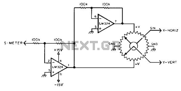
To display polar quantities, which include both the magnitude and direction of a received radio signal, a sine and cosine voltage proportional to an angle corresponding to the antenna direction is required. This setup utilizes a sine-cosine potentiometer connected...
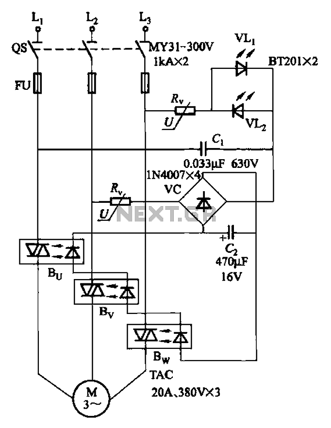
The circuit depicted in Figure 3-93 is integrated with an optical phase sequence protection relay. The circuit in question is designed to provide phase sequence protection using an optical relay mechanism. Optical phase sequence protection relays are crucial in applications...
This circuit utilizes a probe that contains a Clairex 905HN light-dependent resistance element, which is connected to a DC differential amplifier. The amplifier drives a meter with a specially calibrated scale. The article outlines the calibration procedure. A switching...
Audio from the telephone is inductively coupled to the base of Q1, which functions as a preamplifier. This preamplifier provides a gain of approximately 75 dB, boosting the input signal from around 4 mV to about 300 mV peak-to-peak....
The circuit generates a warble-tone alarm signal that simulates the sound of a British police siren. IC1 is configured as an alarm generator, while IC2 operates as a 1 Hz astable multivibrator. The output from IC2 is utilized to...