
GF2A op amp audio amplifier circuit diagram

The audio preamplifier circuit employs an operational amplifier (op-amp) configured for optimal performance in audio applications. The op-amp's design ensures minimal signal distortion, making it suitable for high-fidelity audio systems. The negative feedback mechanism is crucial for maintaining linearity and reducing harmonic distortion, which is particularly important in audio signal processing.
In the circuit, the high-frequency compensation capacitor C1 helps to stabilize the amplifier by controlling the frequency response, preventing unwanted oscillations. The decoupling filter, consisting of C2 and R2, serves to filter out noise from the power supply, ensuring that the op-amp receives a clean voltage supply, which is vital for maintaining audio quality.
The adjustment potentiometer RP1 is used to fine-tune the CMRR, allowing the circuit to effectively reject noise and interference that may affect the audio signal. This is particularly beneficial in environments with significant electromagnetic interference. The second potentiometer, RP2, is integral to the feedback loop, enabling the user to adjust the gain of the amplifier, thus tailoring the output level to match the requirements of subsequent audio processing stages or amplifiers.
The component values specified in the design are selected to optimize performance while keeping the circuit compact. For instance, the choice of capacitors and resistors directly influences the frequency response and gain characteristics of the amplifier. The operational amplifier GF2A is selected for its favorable specifications, including low noise and high gain, making it well-suited for audio applications.
Finally, the use of a small output transformer commonly found in crystal tube radios enhances the circuit's compatibility with various audio sources, ensuring efficient signal transfer and minimizing losses. Overall, the design of this audio preamplifier circuit combines advanced electronic principles with practical component selection to achieve high-quality audio amplification. As shown, the use of the operational amplifier A for audio preamplifier circuit. The advantage is small size, low noise, low power consumption, good consistency. A operational amplifier can achieve a deep negative feedback, while increasing output without distortion. The signal distortion below 1%; voltage gain of the amplifier up to 50 ~ 80dB. Wherein, cl is the high frequency compensation capacitor, c2, R2 decoupling filter circuit. Adjustment potentiometer RPl balances CMRR. Potentiometer RP2 negative feedback element. RP2 adjust the output level can be changed. Component selection: capacitance cl as 82P, c2 to 100p/25v. Resistor R1 is 27kn, R2 is 100n, R3 is 50kn. Potentiometer RPl10kn, RP2 is 100kn. Integrated operational amplifier A with GF2A. Transformer T with Crystal Hugh tube radios commonly used small output transformer instead.
Related Circuits
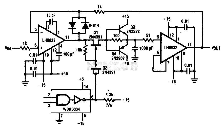
This circuit demonstrates a 10 V acquisition time of 900 ns with 0% accuracy and a droop rate of only 100 µV/ms at an ambient temperature of 25°C. A faster acquisition time can be achieved by using a smaller...
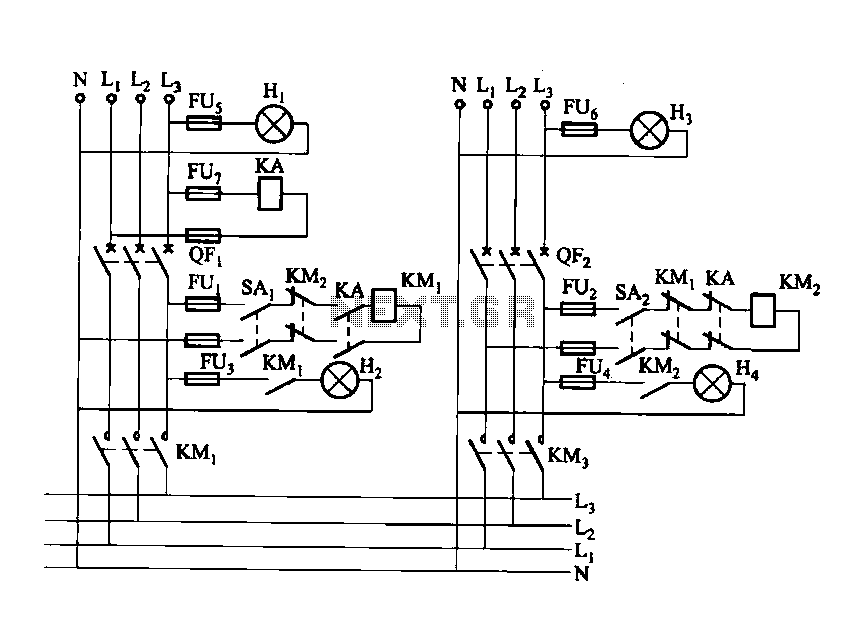
Dual power automatic recovery means one power supply and one standby power supply. When the main power supply is turned off, the standby power supply is automatically activated. Once the main power supply is restored, the system automatically exits...
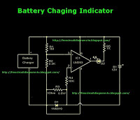
This is a battery charger indicator circuit diagram. When the battery is charging, it is indicated by an LED. This circuit can be used with a 12V battery with a charging current of less than 1A. The battery charger indicator...
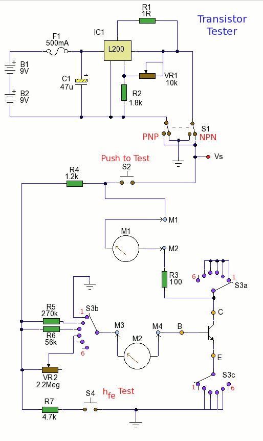
Using the tester is straightforward. Begin with the power off and insert a transistor into the test socket. Set switch S1 for either NPN or PNP configuration and rotate switch S3 to the desired test position. Adjust variable resistor...
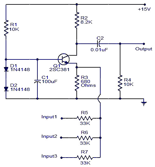
Numerous audio mixer circuits have been published; however, this particular design is among the simplest. This straightforward audio mixer circuit utilizes only a single transistor. The base-emitter junction of the transistor is biased with diodes D1 and D2. The...
The following circuit illustrates a Mains Remote-Alert Circuit Diagram. Features include simple circuitry, with the transmitted signal being conveyed effectively. The Mains Remote-Alert Circuit is designed to provide a notification system that alerts users about the status of mains power....