
battery charger indicator circuit

The battery charger indicator circuit is designed to provide a visual indication of the charging status of a 12V battery. It utilizes a light-emitting diode (LED) to signal when the battery is actively charging. The circuit operates with a charging current of less than 1A, making it suitable for various applications where low-power charging is required.
The primary components of the circuit include a resistor, a diode, and the LED itself. The resistor is used to limit the current flowing through the LED to prevent damage and ensure proper operation. The diode may be included to prevent reverse polarity, ensuring that the circuit functions correctly regardless of the battery's connection orientation.
When the battery is connected to the charger, and the charging process begins, current flows through the circuit. The LED will illuminate, providing a clear visual cue that the battery is charging. This feature is particularly useful in applications where the user may not be present to monitor the charging process continuously.
Additionally, the circuit can be integrated into various battery management systems or used as a standalone indicator for portable devices. Its simplicity and effectiveness make it a valuable addition to any battery charging setup, enhancing user awareness and safety during the charging process.This is battery charger indicator circuit diagram. When the battery charges it shows by the LED this circuit can be used with 12V battery with charging current less than 1A. 🔗 External reference
Related Circuits
Photo. This is the test circuit -the basic driver is only two transistors, two resistors, the circuit was evaluated using a white LED, but when it was time to button it up and archive it, I replaced the expensive...
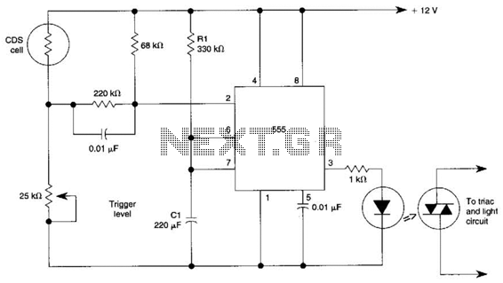
This circuit can control the on/off cycle of a light using a CDS photocell and turn it off after a preset period. The light can only be activated when the CDS cell is in darkness, and it remains on...

This 15V variable power supply electronic project is designed using 2N3055 transistors. The output voltage of this variable power supply can be adjusted in the range between 1.5 and 15 volts. This 2N3055 15V variable power supply can provide...
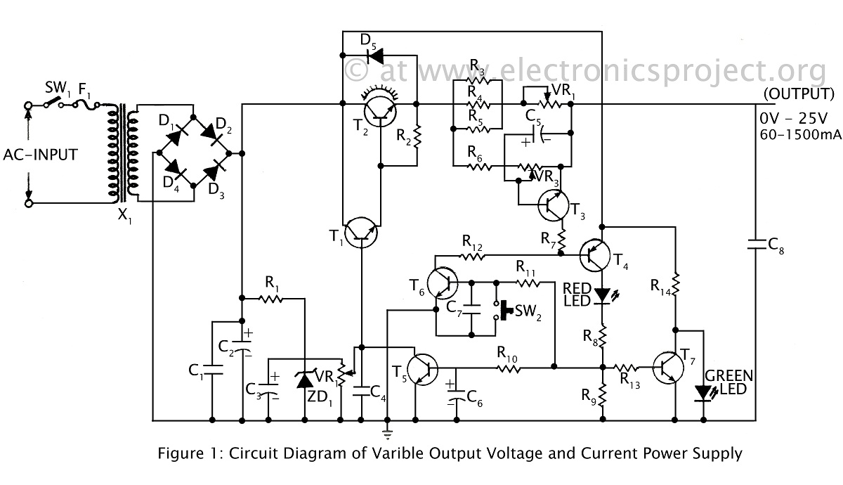
A ripple-free, short-circuit protected variable output voltage and current power supply is presented on this website as a verified project. The circuit diagram includes a description of various power supply circuits. This power supply circuit is designed to provide a...
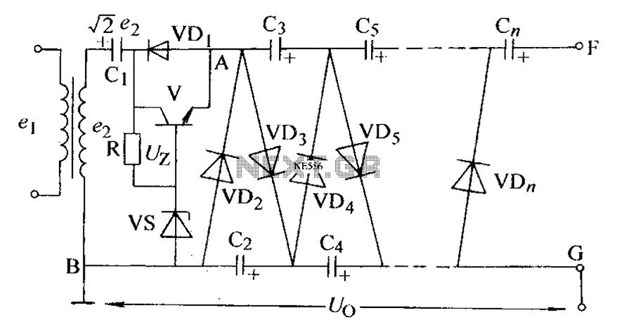
The circuit is an adjustable output voltage regulator type rectifier. It allows for obtaining peak voltage at odd multiples when the output voltage is taken from the circuit feedback (FB). Additionally, the lower point of the capacitor (CB) can...
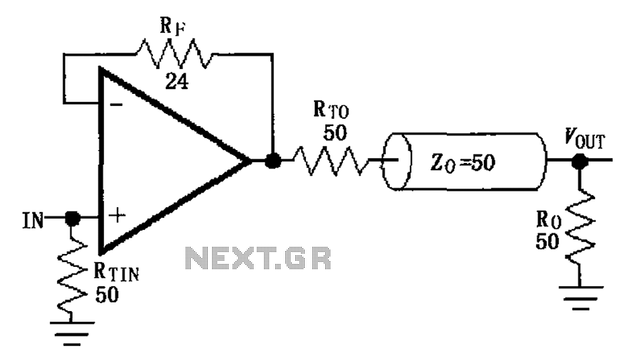
The MAX4450/4451 unity gain line is illustrated in the driving circuit. The MAX4450/4451 features internal compensation, a 24-ohm resistor in series within a feedback loop, along with capacitors and inductors that can reduce the Q value of the feedback...