
Good/Bad Transistor Tester

A good/bad transistor tester typically operates by applying a small voltage to the transistor terminals and measuring the resulting current flow. The tester assesses the transistor's gain, which is a crucial parameter indicating its ability to amplify signals. If the gain is equal to or exceeds the threshold value of 30, the transistor is classified as "good"; otherwise, it is deemed "bad."
The circuit design of a good/bad transistor tester usually incorporates a few essential components, including a power supply, a current measuring device (often an analog or digital multimeter), and a switching mechanism to connect the transistor under test. The tester may feature a simple LED indicator or a digital readout to provide visual feedback on the transistor's status.
In terms of construction, the tester circuit can be built using common electronic components such as resistors, capacitors, and transistors. A typical configuration might include a biasing network to ensure the transistor is operating in the correct region of its characteristic curve. The output stage may utilize an op-amp or a comparator to compare the measured gain against the predefined threshold.
Moreover, the tester can be designed to accommodate various transistor types, including NPN and PNP configurations, by incorporating a switch or jumper settings to adjust the biasing conditions accordingly. This versatility enhances the utility of the tester in diagnosing a wide range of transistors found in electronic devices.
In summary, a good/bad transistor tester is a straightforward yet effective tool for quickly assessing the functionality of transistors, making it an essential instrument for electronics repair and maintenance. Its design emphasizes simplicity and reliability, ensuring accurate results in determining the operational status of transistors.Good/Bad transistor tester means that this instrument can only determine if the transistor is good or bad, nothing more. Any transistor with gain equal to 30.. 🔗 External reference
Related Circuits
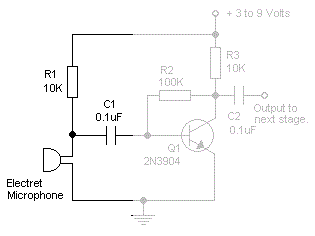
Read the generic sound level from an electret microphone. Several schematics utilize NPN transistors that yield an inverted output (~5V when quiet, ~0V when loud, with linear operation in between). However, a non-inverted output is desired, where a super...
Testing whether a transistor is shorted or open is typically performed using an ohmmeter. The test involves checking if current can flow between the base and emitter or the collector. To effectively test a bipolar junction transistor (BJT) for shorted...
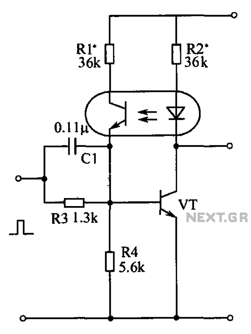
The bistable circuit and optocoupler transistor operate as illustrated in the accompanying figure. Initially, when the supply voltage is applied, the transistor VT is in the off state, resulting in a high output potential. Upon receiving a forward pulse...
This simple circuit is designed to test transistors in a circuit, capable of measuring down to 40 ohms across the collector-base or base-emitter junctions. It is also suitable for checking output power transistors in amplifier circuits. The operation of...
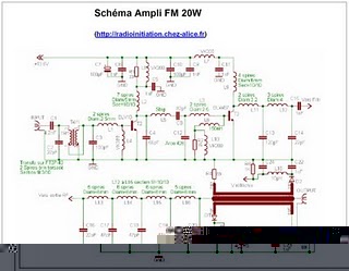
The following circuit illustrates an RF amplifier designed for FM frequencies ranging from 88 to 108 MHz with a broadband configuration. This circuit utilizes the BLV10 transistor. The RF amplifier circuit operates within the FM broadcast band, which is crucial...
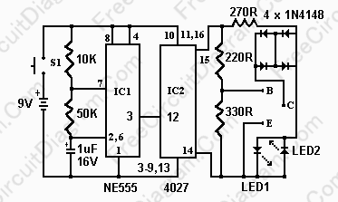
This network wiring tester consists of two components: a transmitter unit, which is powered and installed at the network's starting point, and a passive receiver unit that can be moved from socket to socket. Both units contain eight LEDs,...