
GPS Jammer

The described circuit integrates a GPS receiver with a VCO and an MMIC to facilitate location tracking. The VCO generates a frequency signal that is essential for accurate GPS operation. The MMIC IC3 serves a critical role in amplifying this RF signal, thereby enhancing the overall sensitivity and performance of the GPS module. The power management for the MMIC is crucial, with R3 and L1 working together to provide a stable supply while preventing overcurrent conditions that could lead to thermal runaway or component failure.
The specification of maintaining a current limit around 50 mA is vital for the longevity and reliability of the MMIC. This current threshold balances the need for sufficient gain against the risk of overheating. The circuit may include additional components like bypass capacitors to filter noise and stabilize the power supply to the MMIC.
The use of desoldering wick is a practical aspect of circuit assembly and maintenance. This technique allows for the clean removal of excess solder, which is critical when troubleshooting or modifying the circuit. The application of rosin aids in the process by improving the flow of solder and ensuring a clean joint.
Finally, monitoring the PLL voltage is an essential diagnostic step in ensuring that the GPS receiver is functioning correctly. The PLL is responsible for maintaining the accuracy of the frequency output, and checking the voltage at designated points, such as capacitor C3 or pin 5, provides insight into the operational status of the PLL. This voltage measurement can indicate whether the PLL is locked to the correct frequency, which is crucial for the accurate operation of the GPS system.With a GPS receiver that costs less than a few hundred dollars you can instantly learn your location on the planet-your latitude, longitude, and even altitude-to within a few hundred feet. The output of the VCO is directly connected to a MMIC IC3. This IC amplify the RF signal and feed it to the antenna. The power to the MMIC is feed from R3 and L1. Although I advice you to stay around 50 mA since you can blow the MMIC with to much current. The more current the higher gain and more output jamming power. The desoldering wick is a flattened, braided copper sheath looking for all the world like shielding on phone cord (except that the shielding is tinned) without the cord. I impregnate the wick with some rosin and place it over the legs and bridges of the circuit. The wick is then heated by the soldering iron, and the molten solder flows up the braid by capillary action.
Now, we must make sure that the PLL system is working and the easiest way is to measure the PLL voltage over capacitor C3 or at pin 5 of the PLL. (see schematic) 🔗 External reference
Related Circuits
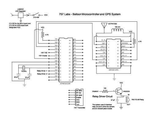
The balloon reached a peak altitude of 103,258 feet. Several factors needed to be considered when launching a payload to this height. Unlike creating an electronics package for sea level, variables such as air pressure, temperature, relative humidity, and...
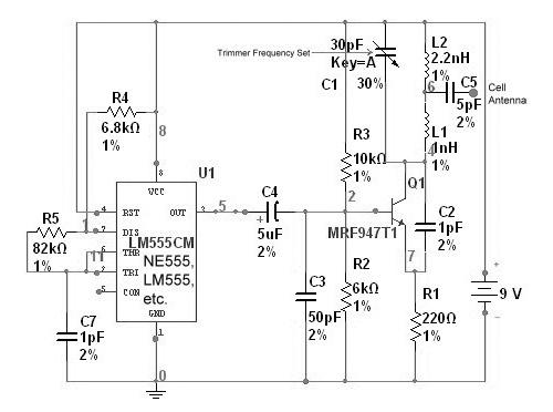
A "Cell Jammer" is simply another term for a "Dirty Transmitter," which transmits within the cellular phone frequency bands. In reality, the more interference it generates, the more effective it is. A cell jammer operates by emitting signals that interfere...
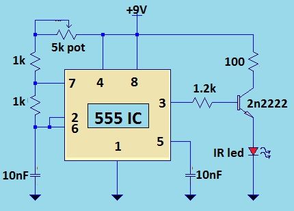
This circuit is designed to disrupt infrared (IR) remote signals, allowing users to override volume settings on a stereo, change TV channels, or create general interference. Key components include a ceramic capacitor, an electrolytic capacitor, a resistor, a battery,...
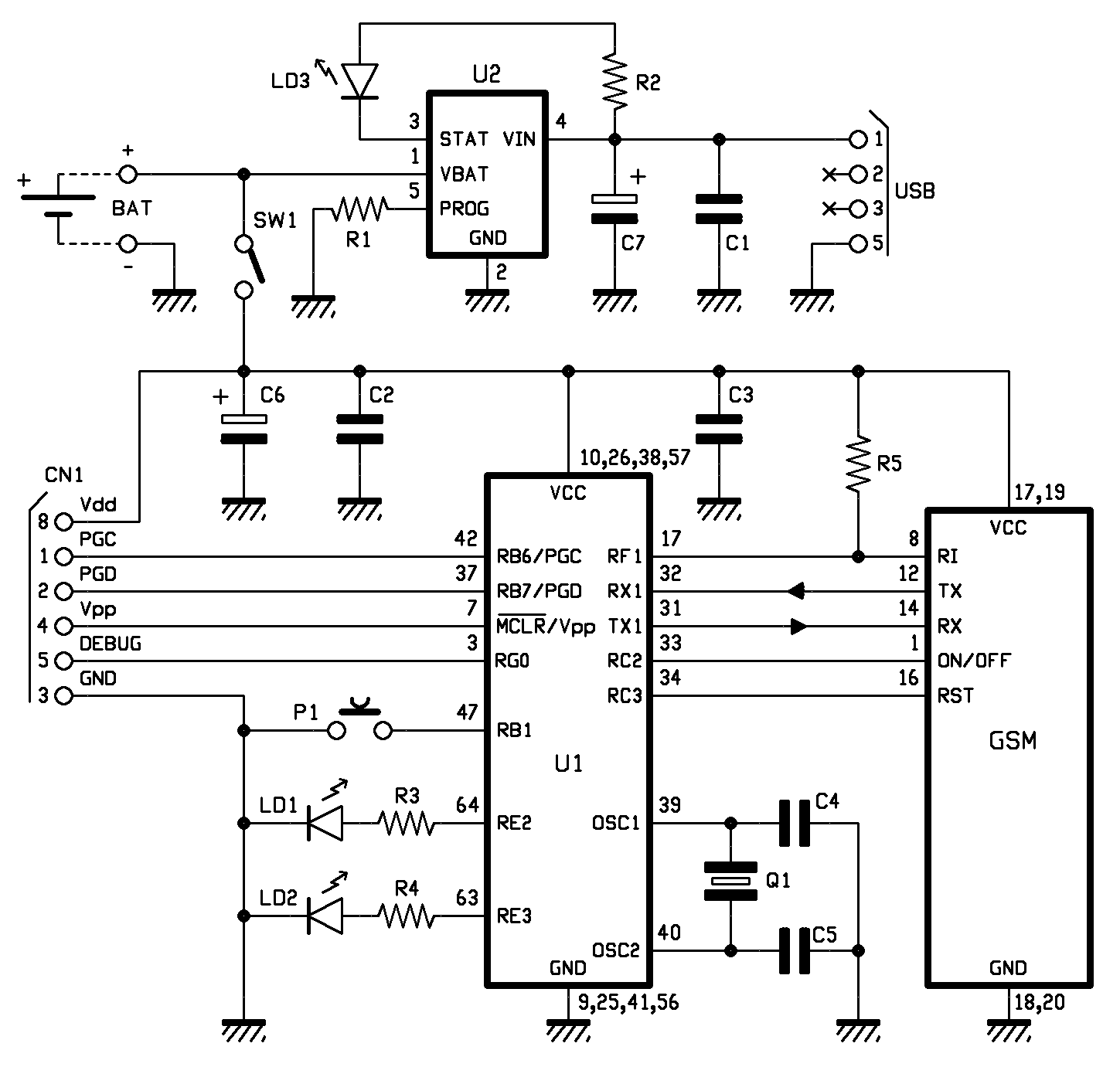
A localizer that does not utilize GPS technology has been developed using the cost-effective SimCom SIM900 module. In previous discussions, the GSM section was presented, and now the complete localization system is introduced. This system allows for object localization...
A circuit designed to block a television and any selected device from receiving signals from a standard remote control. This project involves converting an ordinary remote into a jamming device while maintaining its normal functionality. The chosen remote control...
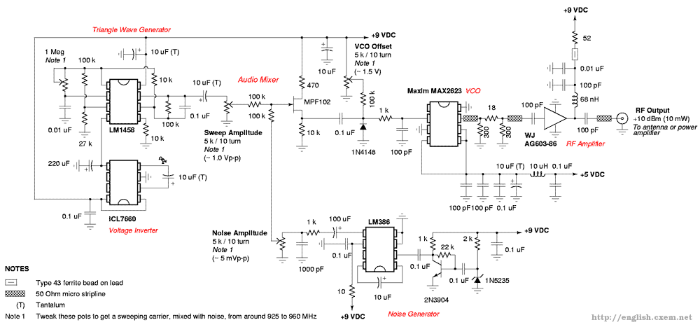
Emits a carrier that sweeps the 925-960 MHz cellular tower transmitter band (handset receive band). The described system functions as a signal generator, specifically designed to emit a carrier wave that sweeps across the frequency range of 925 to 960...