
GSM900 Cellular Jammer

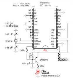
The described system functions as a signal generator, specifically designed to emit a carrier wave that sweeps across the frequency range of 925 to 960 MHz. This frequency band is significant as it corresponds to the cellular tower transmitter band utilized for mobile communication, particularly for handsets receiving signals.
The circuit's core component is a voltage-controlled oscillator (VCO), which is capable of generating a signal at variable frequencies within the specified range. The VCO is typically controlled by a sweep voltage, which allows for the continuous adjustment of the output frequency. A frequency synthesizer may be employed to ensure stability and accuracy of the emitted signal, allowing it to conform to the required specifications for cellular communication.
To achieve the sweeping effect, a linear ramp generator can be utilized to produce a control voltage that varies over time. This ramp voltage is fed into the VCO, enabling it to transition smoothly through the designated frequency range. The output of the VCO is then amplified using a power amplifier to ensure that the signal has sufficient power for transmission.
Additionally, it is essential to incorporate filtering components, such as bandpass filters, to eliminate unwanted harmonics and ensure that the emitted signal remains within the designated frequency range. Proper impedance matching techniques should be applied to maximize power transfer and minimize signal reflections in the transmission line.
In summary, the circuit is designed to generate a stable and adjustable carrier wave that sweeps through the cellular band of 925 to 960 MHz. This capability is crucial for various applications, including testing and calibrating cellular communication systems, ensuring that handsets can effectively receive and process signals within this frequency range.Emits a carrier that sweeps the 925-960 MHz cellular tower transmitter band (handset receive band). 🔗 External reference
Related Circuits
Jammer Store manufactures specialists share their unique experience with you. A detailed guide for skilled electronics fans on how to make your own jammer. The process of constructing a jammer involves a thorough understanding of radio frequency (RF) principles and...
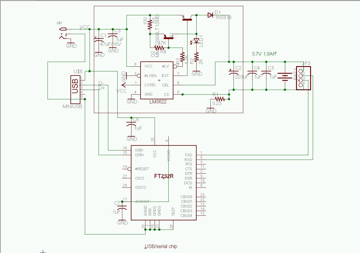
The Jammer is a very small circuit and can fit inside a small plastic box with 9V battery inside. It can be very illegal if you attach an external antenna so don't. adjust frequency by turning trimmer. It is...
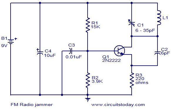
The FM jammer circuit diagram transmits VHF signals. Normally, the powerful oscillation of the circuit interrupts FM signals. Jammers are banned in many regions. The FM jammer circuit operates by generating a strong VHF (Very High Frequency) signal that disrupts...
This is a TV remote control jammer circuit. Remote controls use modulated light to combat interference from background infrared noise. Your room heater, etc. The TV remote control jammer circuit is designed to disrupt the operation of infrared remote controls...
This circuit is designed to detect incoming calls on a cellular phone, even when the phone's ringer is turned off, by utilizing a flashing LED indicator. The device should be positioned a few centimeters away from the cellular phone,...
Hackers listen up. Everyone understands and enjoys the utilitarian benefits that GPS has brought to our lives but what if it didn’t work any more? I suppose you could build some sort of surface to space missile robot that...