
TV Remote Jammer!

To accommodate the 9-volt battery, two posts were removed from the remote. The LEDs were affixed near the existing LED, and the existing switch was utilized to connect the 9-volt battery. A 10k potentiometer is included to adjust the frequency for jamming the targeted device. Fine-tuning of the potentiometer is necessary while the remote is powered on, testing it with the original remote until the jamming effect is achieved. The remote can then be used discreetly to control the device without others realizing the interference.
The project raises concerns regarding legality and safety, with references to FCC regulations and potential risks associated with jamming devices. The circuit's effectiveness relies on overwhelming the infrared receiver of the targeted device with signals that prevent it from distinguishing between the legitimate remote control signals and the jamming signals.
The circuit utilizes a 555 timer configured in astable mode to generate a continuous square wave output. This output is fed into an infrared LED, which emits signals at a frequency adjustable via the potentiometer. The circuit's design ensures that the jamming function does not interfere with the remote's original operation, allowing for seamless transitions between normal use and jamming.
The power supply for the circuit is derived from a 9-volt battery, providing sufficient voltage to drive the infrared LED and the 555 timer circuit. The removal of internal components, such as posts, is a necessary step to create space for the battery while maintaining the integrity of the remote control's exterior.
In summary, this project presents a method for creating a remote control jammer housed within an existing remote, maintaining its functionality while adding a layer of complexity to remote device interactions. The potential implications of such a device highlight the importance of understanding legal boundaries and responsible usage of jamming technology.A circuit that will block my TV and any device I choose from getting a signal from the normal remote control. I turn an ordinary remote into a jammer and the remote still works normally! Watch the video to see it work. I chose to use a Sony remote control (SR-P30) because it has plenty of room inside to add my circuit and a 9 volt battery while keeping the remote fully functional.
I hot glued the circuit inside the remote control. I also had to remove 2 posts to make room for the 9 volt battery. Tape down the LED`s near the existing LED. I used the existing switch on the remote and wired my 9 volt battery to it. You may have to tinker with the 10k pot to get the frequency right for the device you are targeting. Adjust the pot while the remote is `on` and test it with the original remote until the jammer confuses the device. Now, just pull out the remote whenever you need to take control of your device and no one will have any idea what`s going on.
You can bring this to a friends house and drive them nuts! Have fun, be safe! Oh crap, here we go again! Can`t I do a single Instructable without someone claiming it is harmful, illegal, immoral or dangerous Next time I will do one on how to watch paint dry. But then again you could hurt your eyes doing that. Geez! i`ve got the evil genius book, and i reccomend it t anyone who like these sort of gadgets. it has tons of ideas and easy to hard projects to make. BUT from what i remember, yours doesn`t copy the authors idea. OMG. I heard these things violate FCC rule 332. 23. a64 part d, subsection F, paragraph 9. This is so illegal, I can`t believe you do these things. According to my research on the internets, this is very un-american, as only communists make these, and kittens die from exposure to the cancer rays.
In seriousness: how does this jammer work Is it basically so `bright` that the receiver doesn`t distinguish the IR signal from the real remote Sorry, I should go to your website; but at the same time I think an instructable should have more instructions on it, rather than a link to the instructions. This is a cool device nonetheless. would it be possible to make a bug lazer killer (you know like pointing a storong lazer at a bug and watch it cook) you can find that location of the bug in a 3D field useing a sonar device to see anything out of the ordinary feed back ( a distance only sensor will be needed to be triangulated with a second useing the same system, as will a direction only sensor) or a window blocker useing several strong lazers and a similar, but more mission impossible laser field array like the one used in a video of yours for cheap home protection hello.
i loved your videos man! i have the same taste and i used to wonder, would there be any one of this sort. strengthening the remote signal is the easiest and can be implemented. Fortunately, what you say is incorrect. This will not, as you claim, "screw up" any television sets. Please delete your comment as it provides misinformation and is highly misleading. I agree if this damaged a TV I`d be very surprised. Also if this was harmful wouldn`t having more than one IR device in your living room be just as harmful to your TV. Only remote (pun not intended) possibility I see is if steady (or perhaps "dirty", discontinued by being on the edge of useful range or performing flaky because of cold solder points) stream was misinterpreted by TV as some unlisted service command which tweaks some important setting.
To many "ifs" in there, though. Besides, even if it was possible, TV repair service would be able to restore it and no material damage would ensue. 1-these circuit design is something really stupid becuse your Power supply is 9v and diode`s turn on in 1v together "two diode" they need 2v so that means voltage applied on output of 555 timer!
2-afte 🔗 External reference
Related Circuits
Here are the schematics for infrared remotes. This remote transmits a tone using an infrared LED. This tone is decoded by the receiver. Since the receiver only switches when it "hears" the tone, there are no accidental activations. The schematic...
While developing an infrared (IR) extender circuit, a method was needed to measure the relative intensities of various infrared light sources. This circuit is the outcome of that research. A photodiode, specifically the SFH2030, is utilized as the infrared...

The project is developed by Team Stark, with Gilbert as the leader and team members Martin and Janssen. The tasks have been divided into three parts. The first part includes camera control, login database, installer, and network setup, which...
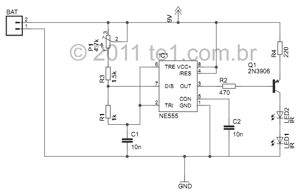
This small device is designed to jam remote controls by directing it at the TV. The circuit utilizes a 555 timer configured as an astable multivibrator, generating a frequency of approximately 38 kHz, which corresponds to the frequency at...
I have seen these devices advertised in magazines, they sell for around £40-£50 and use radio to transmit between receiver and transmitter. This version costs under £5 to make and uses a cable connection between receiver and transmitter. For...
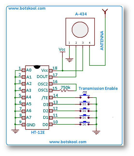
The following circuit illustrates an RF Remote Control Circuit Diagram. This circuit is based on the HT12E IC. Features include the original data in parallel format, where the decoder IC receives the signal through the RF receiver module, utilizing...