
Gray Code Circuit

The Gray Code conversion circuit typically consists of a series of XOR gates that facilitate the transformation from Gray Code to Binary Coded Decimal. The fundamental principle of operation is based on the fact that each bit in the output binary representation is determined by the current and previous bits of the Gray Code input. The first bit of the binary output is directly derived from the first bit of the Gray Code input. Each subsequent bit is generated by applying the XOR operation between the corresponding Gray Code bit and the preceding binary output bit.
For a 4-bit Gray Code to BCD converter, the first XOR gate takes the most significant bit (MSB) of the Gray Code as its output. The second XOR gate combines the second Gray Code bit with the output of the first XOR gate, and this pattern continues for the remaining bits. This systematic approach ensures that only one bit changes at a time, adhering to the Gray Code principle.
To enhance the circuit's versatility, additional XOR gates can be added to accommodate larger bit-width Gray Codes. The 7486 IC, which contains four independent 2-input XOR gates, is ideal for this application. It allows for efficient implementation without the need for complex wiring or additional components, maintaining compactness and reliability.
The circuit can be further expanded to include a BCD to Decimal converter, which interprets the BCD output into a decimal format. This can be achieved using standard logic ICs or a dedicated IC that integrates the necessary logic functions. The design flexibility ensures that the circuit can be adapted for various applications, including digital displays or data processing systems, where Gray Code is utilized for error reduction in digital communication.Gray Code. A positional binary number notation in which any two numbers whose difference is one is represented by expressions that are the same except in one place and differ by only one unit in that place. A code composed of a number of bits assigned in such a way that only one bit changes at each increment, or decrement.
A binary code in which consecutive decimal numbers are represented by binary expressions that differ in the state of one, and only one, one bit. Circuit to convert Gray Code to Binary coded decimal [BCD]. Using standard glue logic ICs; note the circuit works regardless of the particular logic family used, as long as those families will communicate with each other. Manufacturers of Standard Logic The schematic shows a 4-bit converter circuit, but more XOR gates may be added to produce a converter of any number of bits.
A 7486 Quadruple 2-Input Exclusive-OR Gate [74xx86] could be used to implement the Gray code circuit above. There are no Gray code specific converter ICs. A Binary to Gray Code converter can also be made using the same 7486 XOR gates. Instead of feeding the input of the XOR gate from the output of the lower one use its input line. For example XOR-3 has an input tied to output line 2sup3 of XOR-4, tie that input line to Gsup3 instead.
So XOR gate 3 would have an input G2 and G3. This next page shows a Excess-3 Gray Code to Decimal Converter, also refer to the BCD to Decimal Converter or decoder. The circuit can either be made with the chips shown or with the IC that contains the circuit. 🔗 External reference
Related Circuits
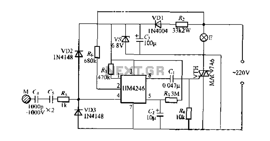
Development and production of a specialized touch dimmer integrated circuit. This circuit features four lighting functions: dark, medium, light, and a touch-sensitive trigger on all four sides. It has low harmonic radiation emission, high touch sensitivity, and stability. It...

This circuit generates sine and square wave signals with frequencies ranging from below 20 Hz to above 20 kHz. The advantage of this circuit diagram is that the output frequency can be adjusted by varying the variable resistor R6. The...
U1 is a 3817 integrated circuit produced by Fairchild Corporation. It is capable of directly driving a display and can operate in both 12-hour and 24-hour formats. Additionally, it can generate a clock sound and activate radios at scheduled...
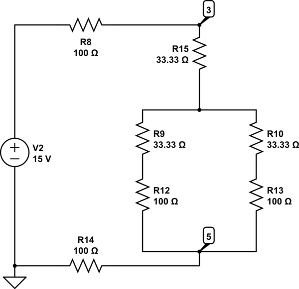
The Delta configuration of resistors R2, R3, and R4 is converted to a Wye (Y) configuration. This conversion is necessary because a voltage divider is typically employed in series circuits. The aim is to determine the total resistance in...
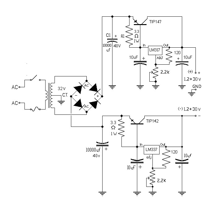
The 10A variable power supply circuit is symmetrical and can provide a symmetrical output voltage ranging from ±1.2 volts to ±30 volts DC, with a maximum current of 10A. This circuit utilizes symmetrical variable voltage regulators LM317 and LM337,...
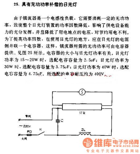
The fluorescent lamp with reactive power compensation operates with a ballast that acts as an inductive load. This inductive load requires reactive power, which leads to a decrease in the power factor of the fluorescent lamp. A lower power...