
The fluorescent with reactive power compensation circuit diagram

The described circuit configuration addresses the issue of reactive power consumption in fluorescent lamp systems. Fluorescent lamps, typically equipped with electromagnetic ballasts, exhibit inductive characteristics that necessitate reactive power for their operation. This requirement can lead to a reduced power factor, which in turn can cause inefficiencies in electrical systems, potentially leading to increased energy costs and reduced performance of connected devices.
Incorporating a capacitor in parallel with the fluorescent lamp's power supply effectively compensates for the inductive reactance introduced by the ballast. By providing the necessary reactive power, the capacitor improves the overall power factor of the system, thereby enhancing the efficiency of energy usage. The selection of capacitor size is critical and must be matched to the power rating of the fluorescent lamp to achieve optimal performance.
For instance, a 15 to 20W fluorescent lamp would require a capacitor with a capacitance of 2.5 µF, while a 30W lamp would necessitate a 3.75 µF capacitor, and a 40W lamp would require 4.75 µF. It is also essential to ensure that the voltage rating of the capacitor is at least 400V to withstand the operating conditions without failure.
This configuration not only improves the power factor but also contributes to a more stable voltage supply from power stations, thus supporting energy conservation efforts and enhancing the reliability of the electrical system. Proper implementation of this reactive power compensation method is crucial for optimizing the performance of fluorescent lighting systems in both residential and commercial applications.The fluorescent with reactive power compensation As ballast is an inductive load. It needs to consume some reactive power, causing the power factor of fluorescent lamp decreases. It affects the ability of full-powered devices, and reduces the voltage of power stations, and it`s harmful to saving electricity. In order to improve power factor, where the using of fluorescent lamps, fluorescent lamp power supply side should be parallel connected a capacitor, so that the ballast`s reactive power can be provided by capacitor. Figure 25 shows. The size of capacitor and fluorescent power is related. Fluorescent power is 15 ~ 20W, matching capacitance is 2. 5 F; fluorescent power is 30w, the optional capacitance is 3. 75 F; fluorescent power is 40w, the optional capacitance is 4. 75 F. The optional capacitor voltage are 400V. 🔗 External reference
Related Circuits

A simple battery charger circuit with reverse polarity indication is presented. The circuit utilizes the L200 integrated circuit, which is a five-pin variable voltage regulator. It can be powered by DC voltage from either a bridge rectifier or a...
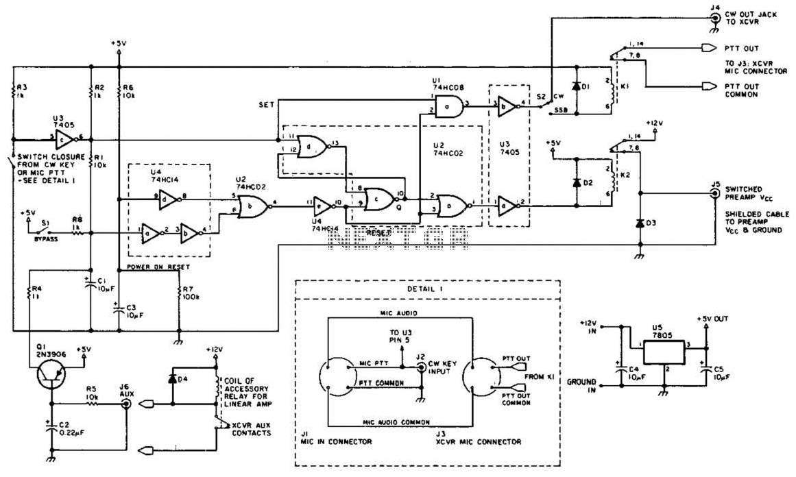
This circuit is beneficial for amateur radio operations in VHF and UHF frequencies, where a mast-mounted antenna preamplifier is employed for reception. The kit manages the transmit-receive (T-R) switching and relay sequencing to prevent high RF levels from being...
The circuit integrates several functions, including a smooth startup for the AC power line, with a one-second delay before connecting to the power supply transformers of the amplifier through relay RL1 and resistor Rx. This delay is designed to...

This is a circuit design for a digital voltmeter with an LED display. It is suitable for measuring the output voltage of a DC power supply. The circuit features a 3.5-digit LED display with a negative voltage indicator and...
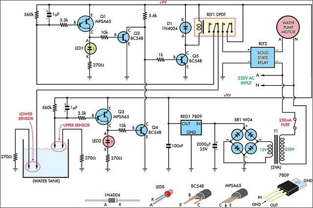
This circuit is designed to effectively fill a header tank for a reticulated water supply on a farm. It supports eight troughs located in various paddocks, where inadequate water supply can have serious repercussions for livestock. Previously, a timer-based...
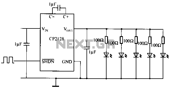
The CP2128 is a low-noise, fixed-frequency step-up DC/DC converter designed for garden applications. It operates within an input voltage range of 2.7V to 4.5V and can generate a stable output voltage of 5V, with a maximum output current of...