
Gray Tube Replication 74

In this context, the discussion revolves around the use of a bridge rectifier circuit, specifically a 1kV configuration utilizing four 6A100 diodes. A bridge rectifier is an essential component in power electronics, converting alternating current (AC) to direct current (DC). The design typically consists of four diodes arranged in a bridge configuration, allowing for full-wave rectification.
The 6A100 diodes are rated for a maximum reverse voltage of 1000V and a forward current of 6A. When designing a bridge rectifier with these components, it is crucial to ensure that the voltage and current ratings are not exceeded during operation to prevent thermal failure or damage to the diodes.
In the case of the mentioned issues, potential causes could include insufficient heat dissipation, leading to thermal runaway, or exceeding the peak inverse voltage (PIV) rating of the diodes during operation. It is advisable to implement adequate heat sinks and thermal management strategies to maintain diode performance within safe limits.
Furthermore, it is important to consider the input AC voltage and the load characteristics connected to the rectifier. Any fluctuations or spikes in the input voltage can lead to unexpected behavior and potential component failure. Protective elements such as fuses or circuit breakers can be integrated into the design to enhance reliability and safety.
In summary, careful consideration of component ratings, thermal management, and protective measures is essential when designing and implementing a bridge rectifier circuit with 6A100 diodes to ensure reliable operation and prevent damage.Geotron, I`ve fried a few mots myself. What kind of bridge do you have leaving it? When I had just a 1kv bridge made from four 6a100`s, I had problems .. 🔗 External reference
Related Circuits
The circuit is simple, yet capable of excellent performance. It is designed specifically for use as an amplifier for the digital sound card in a computer. Audio input can be sourced from any two-channel line level device, such as...

An amplifier designed to drive Sennheiser HD-600 headphones, which have a relatively high impedance. This design ensures ample voltage is available for driving the headphones. Given the large dynamic range of the headphones, the system is engineered to be...
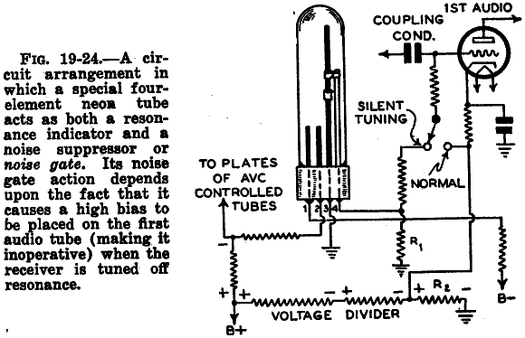
The following two photos illustrate the I/V characteristics of the main anode/cathode current for the Tune-a-Lite 4-element neon tube, which serves as a signal strength meter in certain Fada radios, particularly in the Tune-o-Graph model. A similar 4-terminal Tuneon...
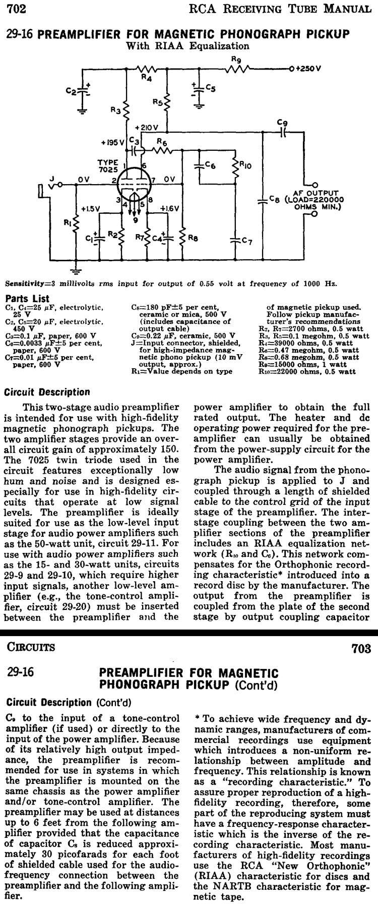
This two-stage audio preamplifier is designed for high-fidelity magnetic phonograph pickups, providing an overall gain of approximately 150. The circuit is sourced from the RCA tube receiving manual and is intended for use with the renowned RCA 7025 twin...
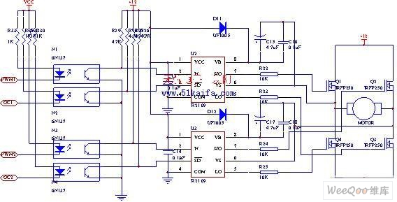
The drive circuit for the electromotor comprises a FET bridge circuit, a FET base drive circuit, a current sensor for the motor drive circuit, and a relay. The FET bridge circuit primarily consists of four high-power MOSFETs, which must...
Miniature vacuum tubes utilizing cathodes made of high-field-emitting carbon nanotubes are being researched at Agere Systems in Murray Hill, NJ. A triode with an amplification factor of 4 has been developed, featuring an anode-cathode spacing of 220 µm, with...