
Stereo Tube Amplifier

The described circuit functions as a two-channel audio amplifier, tailored to enhance the audio output from a digital sound card. The design emphasizes simplicity while maintaining high fidelity, making it suitable for various audio sources, including televisions, CD players, and VCRs.
The circuit typically consists of operational amplifiers (op-amps) configured in a non-inverting amplifier configuration to achieve a gain that is adjustable based on feedback resistor values. Input coupling capacitors are employed to block any DC offset from the audio sources, ensuring that only the AC audio signal is amplified.
The power supply for the amplifier circuit can be derived from a regulated DC source, often +12V and -12V, which is common for op-amp circuits. The output stage may incorporate additional components like output capacitors to prevent DC offset from reaching the speakers or subsequent audio processing stages.
Protection features such as current limiting resistors and thermal shutdown mechanisms might be integrated to prevent damage during overload conditions. Additionally, the layout of the circuit should minimize noise and interference, ensuring that the audio quality remains pristine.
Overall, the circuit provides a robust solution for amplifying audio signals in a compact and efficient manner, making it an excellent choice for enhancing the audio experience in computer-based sound systems.The circuit is simple, yet is capable of excellent performance. I designed it specifically for use as an amplifier for the digital sound card in my computer. Audio input can be from any two-channel line level device such as a television, CD player, or VCR 🔗 External reference
Related Circuits
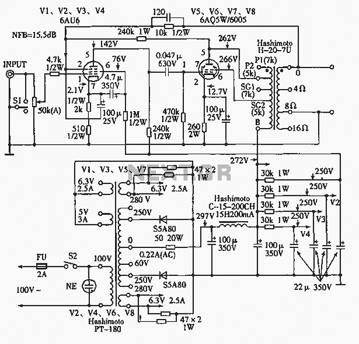
The 6AQ5W / 6005UL four-channel single-ended amplifier circuit is illustrated in the accompanying figure. Only two channels are shown, but it is part of a four-channel system that employs a power transformer for the voltage amplification section. This section...
The history of a pioneering tube developed by Philips Research, which, alongside the magnetron, was one of the most significant tubes during World War II. On the evening of May 9, 1940, the radio valve factory of Philips in...
A common collector amplifier circuit structure and its key components are outlined. The composition of the common collector amplifier circuit is fundamentally similar to that of a common emitter amplifier circuit, with two notable exceptions: one is the collector...
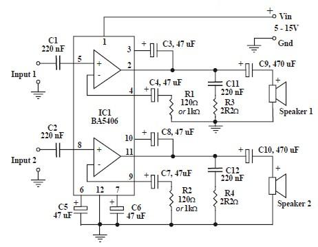
This circuit is based on the BA5406 audio integrated circuit and is capable of providing a maximum output power of 3 watts per channel. This audio circuit is designed for various applications requiring amplified sound output. The BA5406 is a...
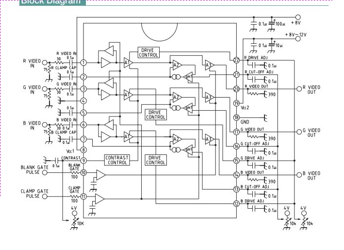
This integrated circuit (IC) is a wideband RGB video amplifier with DC control designed for monitors. It features three matched video amplifiers, a differential input comparator for brightness adjustment, and three matched DC components. The wideband RGB video amplifier is...
An RF force amplifier for FM is essential for amateurs looking to enhance small transmitters, whether they are homemade or commercially available. The presented circuit can deliver 50-60W of RF power with an input control of 15-20W within the...