
Using IRFP250 power tube H-bridge motor drive circuit

The drive circuit is designed to control the operation of an electromotor efficiently. The FET bridge circuit, utilizing four high-power MOSFETs, serves as the core component responsible for converting the input control signals into the appropriate motor drive signals. These MOSFETs are selected based on their switching speed, thermal management capabilities, and current handling specifications to ensure optimal performance and reliability.
The FET base drive circuit is essential for providing the necessary gate drive voltage to the MOSFETs, enabling them to switch on and off effectively. This circuit is typically designed to deliver sufficient gate drive current to ensure rapid switching, which minimizes heat generation and enhances overall efficiency. Proper gate drive design is critical to prevent issues such as cross-conduction and to ensure that the MOSFETs operate within their safe operating area.
The current sensor integrated into the motor drive circuit monitors the current flowing through the electromotor. This feedback mechanism is crucial for protecting the motor and drive circuit from overcurrent conditions, which can lead to damage. The current sensor provides real-time data that can be used for implementing control algorithms, such as current limiting and fault detection.
Additionally, the relay in the circuit serves as a protective element, allowing for the disconnection of the motor from the power supply in case of fault conditions or when the motor needs to be turned off safely. The relay is activated by control signals from the FET base drive circuit, ensuring that the motor can be engaged or disengaged as needed.
Overall, this drive circuit is designed to provide robust and efficient control of an electromotor, incorporating essential components that enhance performance, reliability, and safety in various applications.The drive circuit of electromotor includes a FET bridge circuit, FET base drive circuit,current sensor of motor drive circuit and the relay. FET bridge circuit mainly consists of four high-power MOSFET power tubes,it requires that the power tubes have good switching characteristics,can withstand higher drive current and have a long life.According to motor po..
🔗 External reference
Related Circuits
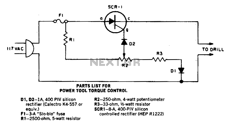
As the speed of an electric drill decreases due to loading, its torque also diminishes. A compensating speed control circuit restores power to the motor. When the drill slows down, the back voltage developed across the motor—connected in series...

This optodetector measures the position of the ball by the amount of light transmitted by the infrared LED. It generates a linear signal across the small area of the detector, rather than simply providing an "on" or "off" output....
The simplest of all motor controllers (besides a straight on/off switch) is the contactor controller. Aaron designed this contactor controller for use in his electric scooter project. It is based around three 12V relays, two 12V batteries, two switches...
More: An electronic schematic is a representation of the components and connections within an electronic circuit. It serves as a blueprint for constructing electronic devices, allowing engineers and technicians to visualize how components interact and function together. The schematic...
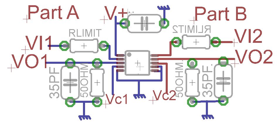
A request for advice regarding the connection diagram of the MAX4685 analog switch is presented. The circuit involves two inputs, VI1 and VI2. The MAX4685 is a low-voltage, dual analog switch designed for low on-resistance and high-speed switching applications. In...
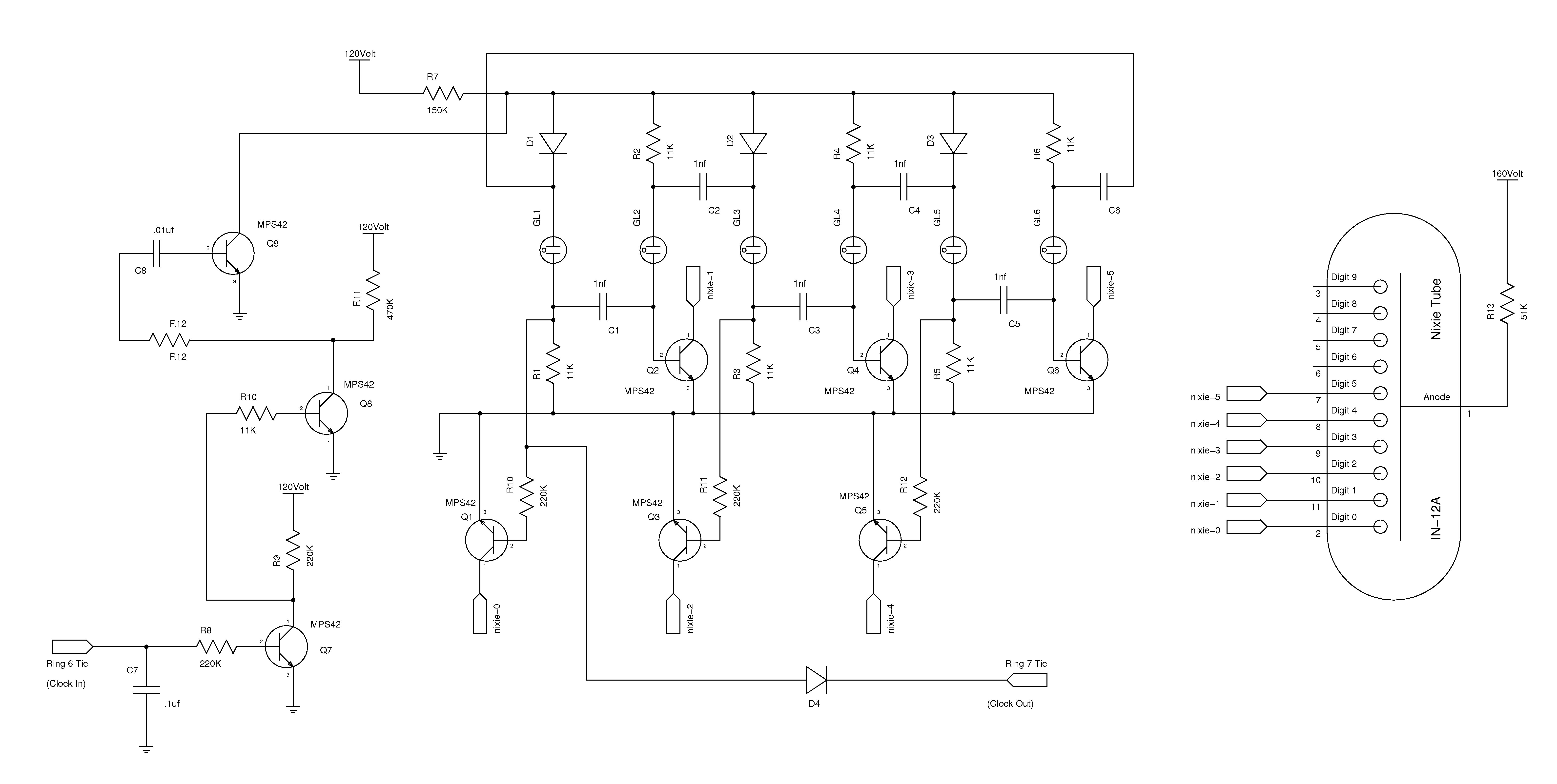
The nixie tube clock consists of a high-voltage power supply, seven ring counters, and an Atmel AVR processor. The power supply is shown in Schematic 1. It takes 12 volts AC and converts it to DC, which drives the...