
Gray Tube Replication 75

The circuit design described involves a high-voltage configuration that integrates diodes capable of handling significant voltage and current levels. The introduction of 1200-volt, 6-amp diodes will enhance the reliability and performance of the circuit, particularly under high-voltage conditions. The relay activation is managed through a transistor circuit, which serves as a switching mechanism, while the square wave generator provides the necessary oscillation to trigger the relay. The optimal operation frequency of approximately 1 Hz suggests that the circuit is designed for low-frequency applications, which may be suitable for certain experimental setups.
The recommendation to replace the 22k resistor with a high self-inductance choke reflects an understanding of energy efficiency in circuit design. Inductors, unlike resistors, do not dissipate energy as heat, thus preserving the energy within the circuit for more effective charging or energy transfer processes. This aligns with historical approaches to energy transfer, especially in systems inspired by Tesla’s work.
The exploration of "negative energy" charging effects indicates an interest in unconventional energy theories, which may lead to unique experimental results. The mention of previous failures, such as the blown 1-ohm resistor, highlights the importance of component ratings and the need for careful monitoring of current draw, especially when working with a vintage high-voltage tube power supply.
The choice of using tinned copper wire for its magnetic efficiency suggests a focus on optimizing the electromagnetic properties of the setup. The uncertainty regarding the engine design points to the complexity of achieving desired outcomes in energy generation or conversion, particularly when considering magnetic piston or repulsion mechanisms.
Overall, the circuit represents a blend of traditional high-voltage techniques with innovative approaches to energy efficiency and experimental exploration, aiming to achieve stable and observable results in future iterations.Using an odd mix of high voltage diodes although I have some 1200 volt, 6 amp diodes on order which will replace the three HV diodes I`m currently using. The Relay is triggered with a basic transistor circuit and square wave generator. The circu it works best at about 1 Hz. Skaght, you have a nice clean setup there, but I`d change one thing: replace that 22k resistor with a choke of high self inductance (or perhaps high NEGATIVE self inductance[bucking coils]), and put one on the negative side also. Tesla always charged through inductors, never resistors. they dissipate energy as heat. Have you seen any "negative energy" battery charging effects I`d love to charge a battery with negative energy and see some of the strange phenomenon that Bearden talks about.
And I agree with you, I wouldn`t be surprised if the battery exploded. The circuit blew up a 1 ohm resistor in some earlier experiments. At least I`d guess that it shouldn`t be a fire hazard as the circuit does seem to run cold. I like the idea of using coils rather than my resistor, but I`m using a vintage high voltage tube power supply for the 200 volt supply. It`s only rated at 100 mA so I want to be careful with it. Resistors let me know exactly how much current I`m drawing. For OU attempts, I`ll switch out to a different source and I`ll keep the coil charging scheme in mind!
The thing about newmans in my setup is about wire to be used not the engine design, he make some tests and find out that tinned copper wire is far more magnetically efficient. Im not sure about engine, it either may be magnetic piston or magnetic repulsion, depending on my (lack of) abillity to calculate components for eds tube power supply, i sow aaron setup on yt, im optimistic about it, but i think ill have problem with perfecting it- to make great discharges constant not only observable, to increase and stabilize frequency.
AND IM REALLY WONDERING HOW IS HE DOING 🔗 External reference
Related Circuits
The circuit is straightforward yet capable of outstanding performance. It has been specifically designed as an amplifier for the digital sound card in a computer. Audio input can be sourced from any two-channel line-level device such as a television,...
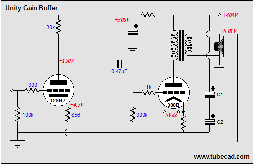
The solid-state, unity-gain power buffer is a well-known concept, but corresponding tube equivalents are less common. While super cathode followers, which are complex and augmented cathode followers with a gain of 0.99, have a long history with various designs...
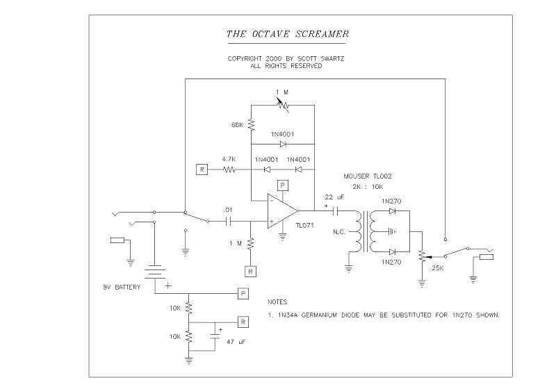
I recently prototyped a Tube Screamer type circuit to refresh my memory about the sound of this pedal. I used a borrowed TS-808 and a Pro Reverb in the mid 80s for several weeks while my modded Twin Reverb...
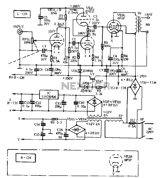
The VE1 preamplifier utilizes a low muscle, low resistance double triode 6N6 configuration, with separate halves for the left and right audio channels. The design operates within the CPI framework. It promotes the use of high-level VE2 household low...
After learning to operate the device, it became evident that inertia posed a significant challenge. The constructed system is notably heavy, making it difficult to initiate motor operation at full speed. Despite having some understanding of physics, practical experience...
The history of a pioneering tube developed by Philips Research, which, alongside the magnetron, was one of the most significant tubes during World War II. On the evening of May 9, 1940, the radio valve factory of Philips in...