
Ground-earth tester

The described circuit operates on a basic principle of series and parallel configurations of lamps, which are typically used for indication or signaling purposes. In this arrangement, lamps 1 and 3 are expected to light up under normal conditions, suggesting that they are in a parallel configuration with a common power source. This configuration allows them to operate independently, ensuring that the failure or activation of one does not affect the others.
Lamp 2's activation serves as a critical diagnostic indicator. Its illumination signifies an anomaly in the circuit, specifically indicating that the cold lead is at 117 volts relative to the ground. This condition may suggest a fault or an unintended path to the power source, which could pose a risk of electrical shock or equipment damage if not addressed.
To ensure safety and reliability, the circuit should be designed with appropriate protective measures, such as fuses or circuit breakers, to prevent overcurrent conditions. Additionally, the use of clearly labeled terminals and color-coded wiring can help in maintaining the integrity of the circuit and ensuring proper installation.
In summary, the circuit's functionality can be monitored effectively by observing the state of the lamps, while the presence of voltage at the cold lead serves as a vital warning sign that should not be overlooked. Proper wiring and adherence to electrical standards are essential for the safe operation of this circuit.The circuit is simple and foolproof if wired correctly. Under normal conditions, only lamps 1 and 3 should be lit. If lamp 2 comes on, the cold lead is 117 volts above ground.
Related Circuits
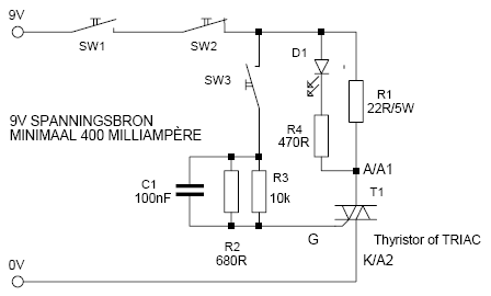
This is a simple but effective thyristor TRIAC tester. Operation at a good thyristor/triac: LED lights when SW3 is pressed. LED turns off when SW2 is pressed. If this occurs, the thyristor/triac is OK. Tip: Hirschmann clips for the...
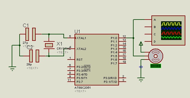
A program is available to control a simple servo motor in both directions. This program has been tested and can be shared for others to benefit from it. It allows the servo motor to rotate in both clockwise and...

This small circuit is designed to verify the basic functionality of an infrared remote control unit. The circuit utilizes a straightforward approach by connecting a piezo buzzer directly to an IR receiver integrated circuit (IC). This configuration is as...
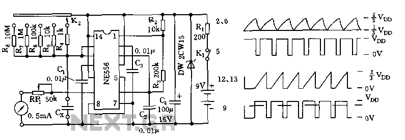
The tester comprises a dual time base circuit using a 556 timer and various RC components. The right side of the circuit features the 556 timer (556 1/2) along with resistors R2, R3, capacitors C2, C3, and additional components...
When building amplifiers, it is often necessary to test transistors, either to verify that they (still) work, or for some esoteric designs it may even be necessary to match certain characteristics. The design featured here is just what you...
A photodiode, SFH2030, serves as an infrared sensor. A MOSFET operational amplifier, CA3140, is utilized in differential mode to amplify the current pulses from the photodiode. LED1, an ordinary colored LED, illuminates when infrared radiation is detected. The output...